![]()
Chapter 1
The Basics
Signals
An audio signal can be transmitted either as a voltage or a current. The construction of the universe is such that almost always the voltage mode is more convenient; consider for a moment an output driving more than one input. Connecting a series of high-impedance inputs to a low-impedance output is simply a matter of connecting them in parallel, and if the ratio of the output and input impedances is high there will be negligible variations in level. To drive multiple inputs with a current output it is necessary to have a series of floating current-sensor circuits that can be connected in series. This can be done,[1] as pretty much anything in electronics can be done, but it requires a lot of hardware and probably introduces performance compromises. The voltage-mode connection is just a matter of wiring.
Obviously, if there’s a current, there’s a voltage, and vice versa. You can’t have one without the other. The distinction is in the output impedance of the transmitting end (low for voltage mode, high for current mode) and in what the receiving end responds to. Typically, but not necessarily, a voltage input has a high impedance; if its input impedance was only 600 Ω, as used to be the case in very old audio distribution systems, it is still responding to voltage, with the current it draws doing so a side issue, so it is still a voltage amplifier. In the same way, a current input typically, but not necessarily, has a very low input impedance. Current outputs can also present problems when they are not connected to anything. With no terminating impedance, the voltage at the output will be very high, and probably clipping heavily; the distortion is likely to crosstalk into adjacent circuitry. An open-circuit voltage output has no analogous problem.
Current-mode connections are not common. One example is the Krell Current Audio Signal Transmission, (CAST) technology, which uses current-mode to interconnect units in the Krell product range. While it is not exactly audio, the 4–20 mA current loop format is widely used in instrumentation. The current-mode operation means that voltage drops over long cable runs are ignored, and the zero offset of the current (i.e. 4 mA = zero) makes cable failure easy to detect: if the current suddenly drops to zero, you have a broken cable.
The old DIN interconnection standard was a form of current-mode connection in that it had voltage output via a high output impedance, of 100 kΩ or more. The idea was presumably that you could scale the output to a convenient voltage by selecting a suitable input impedance. The drawback was that the high output impedance made the amount of power transferred very small, leading to a poor signal-to-noise ratio. The concept is now wholly obsolete.
Amplifiers
At the most basic level, there are four kinds of amplifier, because there are two kinds of signal (voltage and current) and two types of port (input and output). The handy word “port” glosses over whether the input or output is differential or single ended. Amplifiers with differential input are very common—such as all opamps and most power amps—but differential outputs are rare and normally confined to specialised telecoms chips.
Table 1.1 summarises the four kinds of amplifier:
Table 1.1 The four types of amplifier | Amplifier type | Input | Output | Application |
Voltage amplifier | Voltage | Voltage | General amplification |
Transconductance amplifier | Voltage | Current | Voltage control of gain |
Current amplifier | Current | Current | ??? |
Transimpedance amplifier | Current | Voltage | Summing amplifiers, DAC interfacing |
Voltage Amplifiers
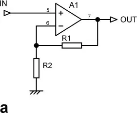
These are the vast majority of amplifiers. They take a voltage input at a high impedance and yield a voltage output at a low impedance. All conventional opamps are voltage amplifiers in themselves, but they can be made to perform as any of the four kinds of amplifier by suitable feedback connections. Figure 1.1a shows a high-gain voltage amplifier (e.g. opamp) with series voltage feedback. The closed-loop gain is (R1 + R2)/R2.
Transconductance Amplifiers
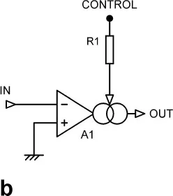
The name simply means that a voltage input (usually differential) is converted to a current output. It has a transfer ratio A = IOUT/VIN, which has dimensions of I/V or conductance, so it is referred to as a transconductance amplifier. It is possible to make a very simple, though not very linear, voltage-controlled amplifier with transconductance technology; differential-input operational transconductance amplifier (OTA) ICs have an extra pin that gives voltage control of the transconductance, which when used with no negative feedback gives gain control. Performance falls well short of that required for quality hi-fi or professional audio. Figure 1.1b shows an OTA used without feedback; note the current-source symbol at the output.
Current Amplifiers
These accept a current in and give a current out. Since, as we have already noted, current-mode operation is rare, there is not often a use for a true current amplifier in the audio business. They should not be confused with current-feedback amplifiers (CFAs) which have a voltage output, the “current” bit referring to the way the feedback is applied in current-mode.[2] The bipolar transistor is sometimes described as a current amplifier, but it is nothing of the kind. Current may flow in the base circuit, but this is just an unwanted side effect. It is the voltage on the base that actually controls the transistor. I have seen it stated that the Hall-effect multiplier is a current amplifier; this is wholly untrue, as the output is a voltage. A true current amplifier can be built by following a transimpedance amplifier with a transconductance amplifier, but this uses two separate stages, with a voltage as an intermediate quantity.
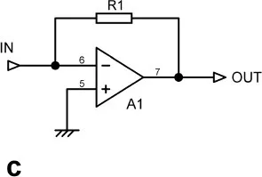
Figure 1.1 a) A Voltage amplifier, b) a transconductance amplifier, c) a transimpedance amplifier
Transimpedance Amplifiers
A transimpedance amplifier accepts a current in (usually single ended) and gives a voltage out. It is sometimes called an I-V converter. It has a transfer ratio A = VOUT/IIN, which has dimensions of V/I or resistance. That is why it is referred to as a transimpedance or transresistance amplifier. Transimpedance amplifiers are usually made by applying shunt voltage feedback to a high-gain voltage amplifier. The voltage amplifier stage (VAS) in most power amplifiers is a transimpedance amplifier. They are used for I-V conversion when interfacing to DACs with current outputs. Transimpedance amplifiers are sometimes incorrectly described as “current amplifiers”.
Figure 1.1c shows a high-gain voltage amplifier (e.g. opamp) transformed into a transimpedance amplifier by adding the shunt voltage feedback resistor R1. The transimpedance gain is simply the value of R1, though it is normally expressed in V/mA rather than ohms.
Negative Feedback
Negative feedback is one of the most useful and omnipresent concepts in electronics. It can be ...