![]()
1
Overview of Fiber Optic Sensors
Eric Udd
CONTENTS
1.1 Introduction
1.2 Basic Concepts and Intensity-Based Fiber Optic Sensors
1.3 Spectrally Based Fiber Optic Sensors
1.4 Interferometric Fiber Optic Sensors
1.4.1 Sagnac Interferometer
1.4.2 Mach–Zehnder and Michelson Interferometers
1.5 Multiplexing and Distributed Sensing
1.6 Applications
Acknowledgment
References
1.1 Introduction
Over the past 20 years two major product revolutions have taken place due to the growth of the optoelectronics and fiber optic communications industries. The optoelectronics industry has brought about such products as compact disc players, laser printers, bar code scanners, and laser pointers. The fiber optic communications industry has revolutionized the telecommunications industry by providing higher performance, more reliable telecommunication links with ever decreasing bandwidth cost. This revolution is bringing about the benefits of high-volume production to component users and a true information superhighway built of glass.
In parallel with these developments, fiber optic sensor technology [1, 2, 3, 4, 5 and 6] has been a major user of technology associated with the optoelectronic and fiber optic communications industries. Many of the components associated with these industries were often developed for fiber optic sensor applications. Fiber optic sensor technology, in turn, has often been driven by the development and subsequent mass production of components to support these industries. As component prices have fallen and quality improvements have been made, the ability of fiber optic sensors to displace traditional sensors for rotation, acceleration, electric and magnetic field measurement, temperature, pressure, acoustics, vibration, linear and angular position, strain, humidity, viscosity, chemical measurements, and a host of other sensor applications has been enhanced. In the early days of fiber optic sensor technology, most commercially successful fiber optic sensors were squarely targeted at markets where existing sensor technology was marginal or, in many cases, nonexistent. The inherent advantages of fiber optic sensors, which include their (1) ability to be lightweight, of very small size, passive, low power, and resistant to electromagnetic interference; (2) high sensitivity; (3) bandwidth; and (4) environmental ruggedness, were heavily used to offset their major disadvantages of high cost and end-user unfamiliarity.
The situation is changing. Laser diodes that cost $3000 in 1979 with lifetimes measured in hours now sell for a few dollars in small quantities, have reliability of tens of thousands of hours, and are widely used in compact disc players, laser printers, laser pointers, and bar code readers. Single-mode optical fiber that cost $20/meter in 1979 now costs less than $0.10/meter, with vastly improved optical and mechanical properties. Integrated optical devices that were not available in usable form at that time are now commonly used to support production models of fiber optic gyros. Also, they could drop in price dramatically in the future while offering ever more sophisticated optical circuits. As these trends continue, the opportunities for fiber optic sensor designers to produce competitive products will increase and the technology can be expected to assume an ever more prominent position in the sensor marketplace. In the following sections the basic types of fiber optic sensors being developed are briefly reviewed, followed by a discussion of how these sensors are and will be applied.
1.2 Basic Concepts and Intensity-Based Fiber Optic Sensors
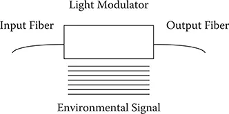
Fiber optic sensors are often loosely grouped into two basic classes referred to as extrinsic, or hybrid, fiber optic sensors and intrinsic, or all-fiber, sensors. Figure 1.1 illustrates the case of an extrinsic fiber optic sensor.
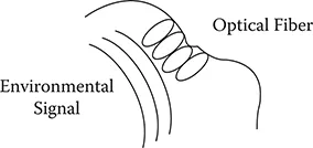
In this case an optical fiber leads up to a “black box” that impresses information onto the light beam in response to an environmental effect. The information could be impressed in terms of intensity, phase, frequency, polarization, spectral content, or other methods. An optical fiber then carries the light with the environmentally impressed information back to an optical and/or electronic processor. In some cases the input optical fiber also acts as the output fiber. The intrinsic or all-fiber sensor shown in Figure 1.2 uses an optical fiber to carry the light beam, and the environmental effect impresses information onto the light beam while it is in the fiber. Each of these classes of fibers in turn has many subclasses with, in some cases, sub-subclasses [1] that consist of large numbers of fiber sensors.
FIGURE 1.1
Extrinsic fiber optic sensors consist of optical fibers that lead up to and out of a “black box” that modulates the light beam passing through it in response to an environmental effect.
FIGURE 1.2
Intrinsic fiber optic sensors rely on the light beam propagating through the optical fiber being modulated by the environmental effect either directly or through environmentally induced optical path length changes in the fiber itself.
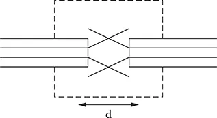
FIGURE 1.3
Closure and vibration fiber optic sensors based on numerical aperture can be used to support door closure indicators and measure levels of vibration in machinery.
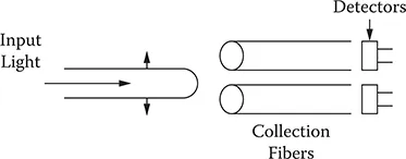
In some respects the simplest type of fiber optic sensor is the hybrid type that is based on intensity modulation [7,8]. Figure 1.3 shows a simple closure or vibration sensor that consists of two optical fibers held in close proximity to each other. Light is injected into one of the optical fibers; when it exits, the light expands into a cone of light whose angle depends on the difference between the index of refraction of the core and cladding of the optical fiber. The amount of light captured by the second optical fiber depends on its acceptance angle and the distance d between the optical fibers. When the distance d is modulated, it in turn results in an intensity modulation of the light captured.
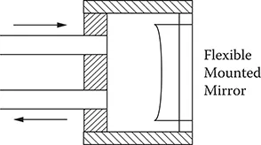
FIGURE 1.4
A numerical aperture fiber sensor based on a flexible mirror can be used to measure small vibrations and displacements.
FIGURE 1.5
A fiber optic translation sensor based on numerical aperture uses the ratio of the output on the detectors to determine the position of the input fiber.
A variation on this type of sensor is shown in Figure 1.4. Here a mirror is used that is flexibly mounted to respond to an external effect such as pressure. As the mirror position shifts, the effective separation between the optical fibers shifts with a resultant intensity modulation. These types of sensors are useful for such applications as door closures where a reflective strip, in combination with an optical fiber acting to input and catch the output reflected light, can be used.
With two optical fibers arranged in a line, a simple translation sensor can be configured as in Figure 1.5. The output from the two detectors can be proportioned to determine the translational position of the input fiber.
Several companies have developed rotary and linear fiber optic position sensors to support applications such as fly-by-light [9]. These sensors attempt to (1) eliminate electromagnetic interference susceptibility to improve safety, and (2) lower shielding needs to reduce weight. Figure 1.6 shows a rotary position sensor [10] that consists of a code plate with variable reflectance patches placed so that each position has a unique code. A series of optical fibers is used to determine the presence or absence of a patch.
An example of a linear position sensor using wavelength division multiplexing (WDM) [11] is illustrated by Figure 1.7. Here a broadband light source, which might be a light-emitting diode, is used to couple light into the system. A single optical fiber is used to carry the light beam up to a WDM element that splits the light into separate fibers that are used to interrogate the encoder card and determine linear position. The boxes...