eBook - ePub
Electromagnetic Compatibility
Principles and Applications, Second Edition, Revised and Expanded
- 864 pages
- English
- ePUB (mobile friendly)
- Available on iOS & Android
eBook - ePub
Electromagnetic Compatibility
Principles and Applications, Second Edition, Revised and Expanded
About this book
This totally revised and expanded reference/text provides comprehensive, single-source coverage of the design, problem solving, and specifications of electromagnetic compatibility (EMC) into electrical equipment/systems-including new information on basic theories, applications, evaluations, prediction techniques, and practical diagnostic options for preventing EMI through cost-effective solutions.
Offers the most recent guidelines, safety limits, and standards for human exposure to electromagnetic fields!
Containing updated data on EMI diagnostic verification measurements, as well as over 900 drawings, photographs, tables, and equations-500 more than the previous edition-Electromagnetic Compatibility: Principles and Applications, Second Edition:
Trusted by 375,005 students
Access to over 1.5 million titles for a fair monthly price.
Study more efficiently using our study tools.
Information
1
Introduction to EMI and the Electromagnetic Environment
1.1 Introduction to Electromagnetic Interference (EMI)
This chapter introduces a few of the important coupling modes involved in electromagnetic interference (EMI) as well as some EMI regulations. Both of these topics will be addressed in more detail in subsequent chapters. In addition, this chapter presents data on average and worst-case electromagnetic emissions found in the environment. This data is useful in evaluating the severity of a given electromagnetic environment and in predicting electromagnetic compatibility (EMC) for equipment operated in these environments.
1.1.1 Effects of Electromagnetic Interference
The effects of EMI are extremely variable in character and magnitude, ranging from simple annoyance to catastrophe. Some examples of the potential effects of EMI are
- Interference to television and radio reception
- Loss of data in digital systems or in transmission of data
- Delays in production of equipment exhibiting intraunit, subsystem, or system-level EMI
- Malfunction of medical electronic equipment (e.g., neonatal monitor, heart pacemaker)
- Malfunction of automotive microprocessor control systems (e.g., braking or truck anti-jackknife systems)
- Malfunction of navigation equipment
- Inadvertent detonation of explosive devices
- Malfunction of critical process-control functions (e.g., oil or chemical industry)
To correct EMI problems that occur after equipment is designed and in production is usually expensive and results in program delays, which may adversely affect the acceptance of a new product. It is preferable to follow good EMC engineering practice during the equipment design and development phases. Our goal should be to produce equipment capable of functioning in the predicted or specified electromagnetic environment and that does not interfere with other equipment or unduly pollute the environment—that is, to achieve EMC.
The techniques of EMC prediction described in subsequent chapters will aid in meeting the goal of EMC when applied at the design stage. These same techniques of analysis and modeling are applicable to EMI control and problem solving or in the location of out-of-specification emissions. It is in the area of emission reduction where analysis is most likely to be supplemented by measurement and diagnostic intervention. However, the value of simple EMI measurements made as early as feasible in the design, breadboard, and prototype phases cannot be emphasized enough.
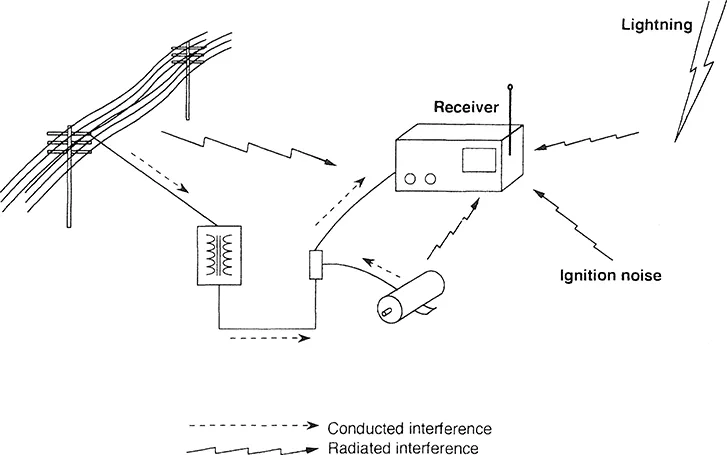
Figure 1.1 Possible sources of ambient noise and how they may be coupled into a receiver.
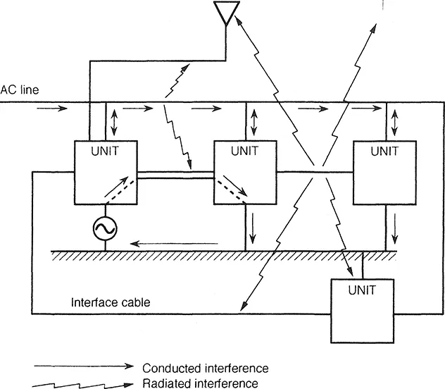
Figure 1.2 Some of the possible interference coupling modes within a system.
1.1.2 Electromagnetic Interference Coupling Modes
For EMI to exist there must be a source of emission, a path for the coupling of the emission, and a circuit, unit, or system sensitive to the received noise. Figures 1.1–1.3 illustrate that two modes of coupling, radiated and conducted, can exist. In the near field, the radiated coupling may be either a predominantly magnetic (H) field coupling or an electric (E) field coupling, whereas the coupling in the far field will be via electromagnetic waves exhibiting a fixed ratio of the E to H field strengths. A more rigorous definition of near and far field is presented in Section 2.2.1. Suffice it to say here that the near field is in close proximity to a source and the far field is beyond some determined distance from the source.
For circuits and conductors in close proximity we consider the coupling, or crosstalk, to be via mutual inductance and intercircuit capacitance, although one of these modes usually predominates. The source of noise may be power lines, signal lines, logic (especially clocks and data lines), or current-carrying ground connections. The conducted path may be resistive or contain inductance or capacitance, intentional or otherwise, and it is often a combination of these. The reactive components often result in resonances, with their concomitant increase or decrease in current at the resonant frequencies.
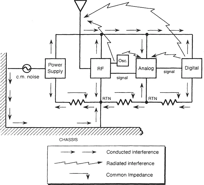
Figure 1.3 A few of the intraequipment (unit) coupling modes.
1.2 Introduction to Electromagnetic Interference Regulations
The level of immunity built into equipment depends on how critical the correct functioning of the equipment is and on the electromagnetic environment in which it is designed to operate. Many EMI requirements take the criticality and environment into account by classifying equipment and by imposing different susceptibility test levels on the different classes.
EMI can be considered a form of environmental pollution; in order to reduce the impact of this pollution, some control on the environmental level of conducted and radiated emissions of noise is necessary.
Many countries impose commercial regulations on the emissions from data-processing equipment; industrial, scientific, and medical (ISM) equipment; vehicles; appliances; etc. In some instances standards are developed by a nongovernmental agency, such as the Society of Automotive Engineers (SAE), and are not necessarily mandatory. The majority of military regulations and standards, and some commercial specifications, also require that equipment be demonstrated immune to susceptibility test levels.
Chapter 9 describes the typical EMI regulations and requirements and EMI measurement techniques.
1.2.1 Military Regulations
The options are limited for manufacturers of equipment that must meet specified requirements. The military requirements are intended to be tailored to the specific electromagnetic environment by the procuring agency; however, this is seldom implemented. Should equipment fail specified military requirements and, after analysis or measurement, the environment be found more benign than the specified levels indicate, then the possibility exists for the procuring agency to grant a waiver on the specification limit. A more satisfactory approach is to specify realistic limits in the first place. The difficulty here is that the requirements are location dependent. That is, the proximity of equipment to transmitting antennas or other equipment or the number of units connected to the same power supply varies from case to case. Where equipment is intended for operation in a known location, the limits may be readily tailored to the environment.
1.2.2 Commercial Regulations
The manufacturers of equipment that must meet commercial requirements are seldom if ever awarded a waiver, and the limits are inflexible. To date only the countries of the European Union (EU) require immunity testing. Some manufacturers who want to market in non-EU countries may consider this an advantage until the equipment is found to be susceptible in a typical environment.
1.2.3 Unregulated Equipment
For the manufacturers of equipment to which no regulations apply but who want to achieve EMC either for the sake of customer satisfaction or safety or to minimize the risk of a lawsuit, the choice is either to design for a realistic worst-case environment or to define the environment with an existing EMI standard. We define a realistic worst case as either a measured maximum environment in a large sample of similar environments or a predicted maximum where all the mitigating factors have been considered.
In an ideal world, specified limits would be close to the realistic worst-case environment, whereas, as we shall see in Section 1.3, this is not always true.
1.3 Electromagnetic Environment
The information in this section is intended to provide a comparison of the various worst-case environments and to provide guidelines to equipment designers and those writing procurement specifications.
Sources of EMI can be divided into natural and manmade, with, in most cases, the natural sources of radiation present at a much lower level than the manmade. The majority of unintentional emissions occupy a wide range of frequencies, which we may call broadband in a nonstrict sense of the term. Intentional emissions, such as radio and television transmissions, are termed narrowband and in the strictest sense of the term are emissions that occur at a single frequency or are accompanied by a few frequencies at the sidebands. The strict definitions of narrowband and broadband, as used in EMI measurements, and addressed in Chapter 9, are dependent on both receiver bandwidth and the pulse repetition rate of the source.
Electric field strength is measured in volts/m, as described in Section 2.1. Another unit of measurement is the dBµV/m. The unit of broadband field strength as used in military standards is dBµV/m/MHz. Here the reference bandwidth of 1 MHz is included in the unit. Another unit is the dBµV/m/kHz, where the reference bandwidth is 1 kHz.
For the sake of comparison to other sources of broadband noise, we will arbitrarily use the military MIL-STD 461 RE02 limit for broadband emission from equipment measured at a distance of 1 meter from the source. Figure 1.4 is a reproduction of the RE02 limit for spacecraft. The RE02 limit is more stringent than commercial limits on broadband noise. For example, the West German Commercial Regulation contained in VDE 0875 for broadband limits, when scaled to a 1-meter measuring distance and converted to the 1 -MHz reference bandwidth, imposes a limit of 78.5 dBµV/m/MHz from 30 to 300 MHz. This limit is 13.5 dB above RE02 at 200 MHz and 4 dB and 8.5 dB above at 30 MHz and 300 MHz, respectively. These limits are presented in greater detail in Section 9.4.
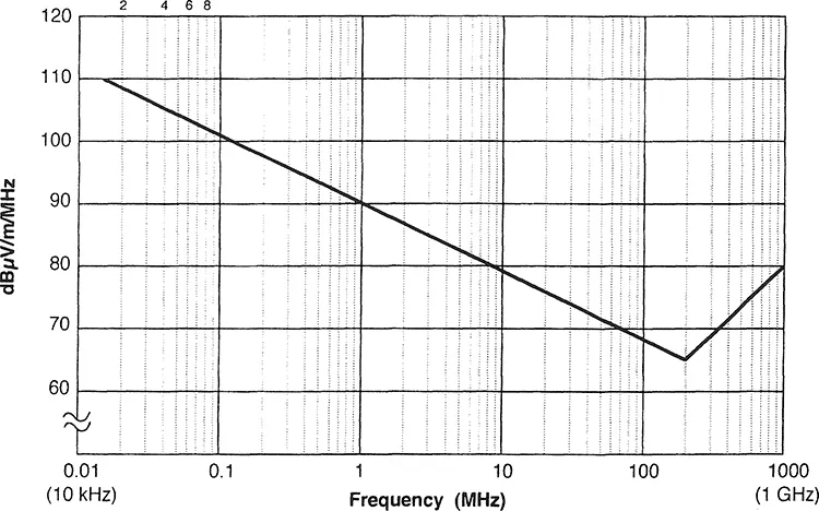
Figure 1.4 RE02 broadband emission limits for spacecraft.
The remainder of this chapter deals with radiated and conducted components of the electromagnetic environment. The radiated electromagnetic environment is treated in Sections 1.3.1–1.3.3 and the conducted electromagnetic environment in Section 1.3.4.
1.3.1 Natural Sources of Electromagnetic Noise
Natural sources of electromagnetic noise are
- Atmospheric noise produced by electrical discharges occurring during thunderstorms
- Cosmic noise from the Sun, Moon, stars, planets, and galaxy
Atmospheric noise is produced predominantly by local thunderstorms in the summer and by tropical-region thunderstorms in the winter. The electromagnetic emissions from thunderstorms are propagated over distances of several thousand kilometers by an ionospheric sky wave, and thus potential EMI effects are no...
Table of contents
- Cover Page
- Half title
- Title Page
- Copyright Page
- Preface
- Contents
- Chapter 1 Introduction to EMI and the Electromagnetic Environment
- Chapter 2 Introduction to E and H, Near and Far Fields, Radiators, Receptors, and Antennas
- Chapter 3 Typical Sources and Characteristics of Radiated and Conducted Emissions
- Chapter 4 Crosstalk and Electromagnetic Coupling Between PCB Tracks, Wires, and Cables
- Chapter 5 Components, Emission Reduction Techniques, and Noise Immunity
- Chapter 6 Electromagnetic Shielding
- Chapter 7 Cable Shielding, Coupling from E and H Fields, and Cable Emissions
- Chapter 8 Grounding and Bonding
- Chapter 9 EMI Measurements, Control Requirements, and Test Methods
- Chapter 10 Systems EMC and Antenna Coupling
- Chapter 11 Printed Circuit Boards
- Chapter 12 EMI and EMC Control, Case Studies, EMC Prediction Techniques, and Computational Electromagnetic Modeling
- Appendix 1 Characteristic Impedance of Conductors, Wires, and Cables
- Appendix 2 Units and Conversion Factors
- Appendix 3 Electric Field Strength to Magnetic Field to Power Density Conversions
- Appendix 4 Commonly Used Related Formulas
- Appendix 5 Data on Bare Solid Copper Wire (Dimensions, Weight, and Resistance)
- Index
Frequently asked questions
Yes, you can cancel anytime from the Subscription tab in your account settings on the Perlego website. Your subscription will stay active until the end of your current billing period. Learn how to cancel your subscription
No, books cannot be downloaded as external files, such as PDFs, for use outside of Perlego. However, you can download books within the Perlego app for offline reading on mobile or tablet. Learn how to download books offline
Perlego offers two plans: Essential and Complete
- Essential is ideal for learners and professionals who enjoy exploring a wide range of subjects. Access the Essential Library with 800,000+ trusted titles and best-sellers across business, personal growth, and the humanities. Includes unlimited reading time and Standard Read Aloud voice.
- Complete: Perfect for advanced learners and researchers needing full, unrestricted access. Unlock 1.5M+ books across hundreds of subjects, including academic and specialized titles. The Complete Plan also includes advanced features like Premium Read Aloud and Research Assistant.
We are an online textbook subscription service, where you can get access to an entire online library for less than the price of a single book per month. With over 1.5 million books across 990+ topics, we’ve got you covered! Learn about our mission
Look out for the read-aloud symbol on your next book to see if you can listen to it. The read-aloud tool reads text aloud for you, highlighting the text as it is being read. You can pause it, speed it up and slow it down. Learn more about Read Aloud
Yes! You can use the Perlego app on both iOS and Android devices to read anytime, anywhere — even offline. Perfect for commutes or when you’re on the go.
Please note we cannot support devices running on iOS 13 and Android 7 or earlier. Learn more about using the app
Please note we cannot support devices running on iOS 13 and Android 7 or earlier. Learn more about using the app
Yes, you can access Electromagnetic Compatibility by David Weston in PDF and/or ePUB format, as well as other popular books in Technology & Engineering & Cyber Security. We have over 1.5 million books available in our catalogue for you to explore.