- 592 pages
- English
- ePUB (mobile friendly)
- Available on iOS & Android
eBook - ePub
Protective Relaying for Power Generation Systems
About this book
Power outages have considerable social and economic impacts, and effective protection schemes are crucial to avoiding them. While most textbooks focus on the transmission and distribution aspects of protective relays, Protective Relaying for Power Generation Systems is the first to focus on protection of motors and generators from a power generation perspective. It also includes workbook constructions that allow students to perform protection-related calculations in Mathcad® and Excel®.
This text provides both a general overview and in-depth discussion of each topic, making it easy to tailor the material to students' needs. It also covers topics not found in other texts on the subject, including detailed time decrement generator fault calculations and minimum excitation limit. The author clearly explains the potential for damage and damaging mechanisms related to each protection function and includes thorough derivations of complex system interactions. Such derivations underlie the various rule-of-thumb setting criteria, provide insight into why the rules-of-thumb work and when they are not appropriate, and are useful for post-incident analysis. The book's flexible approach combines theoretical discussions with example settings that offer quick how-to information.
Protective Relaying for Power Generation Systems integrates fundamental knowledge with practical tools to ensure students have a thorough understanding of protection schemes and issues that arise during or after abnormal operation.
Trusted by 375,005 students
Access to over 1.5 million titles for a fair monthly price.
Study more efficiently using our study tools.
Information
1 Generator Normal Operations
1.1 The Sample System
Before we begin to analyze the various malfunctions that can befall a generator and the connected auxiliary system, we must have an understanding of the parameters that define normal operation. Our review of generator and generator auxiliary protection will be based on the sample system shown in Figure 1.1. During normal operations, the generator supplies power to the grid through the Generator Step Up (GSU) transformer and to auxiliary loads at 4.16 kV buses A and B through auxiliary transformers. When the unit is off line, the auxiliary load is supplied from the auxiliary transformer at Bus B.
The GSU transformer connects to a moderate strength power system. With all lines in service, the power system and GSU transformer appear as a 14.8% impedance at the generator terminals. Line A is the strongest line connected to the 69 kV bus; its outage increases the impedance seen by the generator to 29%.
The system voltage also varies. During light load periods the voltage drop through system components such as lines and transformers is minimal. As load increases, the increased voltage drop caused by the flow of Watts and Vars through these components causes system voltage to fall. Because these power system components are highly inductive, the voltage drop caused by an amp of reactive current is greater than that caused by an amp of real current.
The system voltage regulation between light and peak load is amplified by the reactive characteristic of the long high-voltage (HV) transmission lines. These lines behave as capacitors when lightly loaded. The Vars they produce flow into the system, boosting voltage just as distribution capacitors do. As the HV line loading increases, the line characteristic changes from capacitive to inductive. At peak system load, the Vars consumed by HV lines significantly increases system voltage drop.
During light load periods, generators may be required to operate with reduced field current, consuming excess Vars from the system, to reduce system voltage. At peak system load, generators operate near full field current, supplying Vars to support system voltage.
It is not desirable to operate generators at rated Var output in peak load situations if the system is in a normal configuration. A portion of the generators’ reactive capability should be held in reserve to boost voltage in the event of a forced outage of a major tie line or generator.
Maximum system voltages would be anticipated at night in the spring and fall. Minimum system voltages typically occur during the day in the summer and winter when the system load is at peak. These variations in system configuration and voltage have a significant effect on the operation of the generator and associated auxiliary equipment, as will be seen later in this chapter.
1.2 Generator Capability
The proper application of protective relaying requires knowledge of the operating range of each component and an understanding of the interactions of the generating unit and the power system. First we will look at component ratings.
The nameplate rating of our sample system generator is 104.4 MVA at 0.85 power factor, 13.8 kV. This defines only one limiting point of operation for the machine. It is logical to assume that a reduction in MVAR output would allow some increase in MW output and that a reduction in MW would allow higher MVAR output.
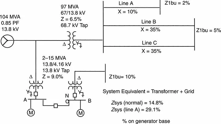
Figure 1.1 System online.
These allowable variations are defined by the generator capability curve, which is provided by the manufacturer. Figure 1.2 is such a curve plotted for a hydrogen-cooled generator. It defines the Watt/Var operating limit as a function of coolant pressure. Note that the maximum design coolant pressure for the generator defines the outermost boundaries, 75# H2. The actual coolant pressure for an operating unit is often less than the design maximum pressure.
The capability curve shown is for a steam-driven generator with a cylindrical rotor. It is a composite of three distinct limits. The right-hand section, between the B and C, represents the limit imposed by the ampere rating of the stator winding. The ampere rating of the field winding imposes the limit between A and B, which limits the output of Vars into the power system. These are termed “lagging Vars.” The bottom limit, C to D, defines the maximum Vars the generator can consume from the power system. These are termed “leading Vars.” This limit is the result of heating in the end laminations of the stator core. It is caused by flux that flares from the end of the stator when the generator is operating at low field current. The capability curve is normally plotted at the rated terminal voltages for the generator.
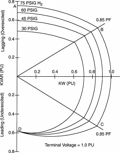
Figure 1.2 Generator capability curve.
The capability curve for a hydro unit will differ from that of a steam unit. Hydro units are of salient pole construction and do not have end core regions. Thus they will only have two distinct limits. The field circuit imposed lagging Var limit from A to B and the stator winding current limit which for a hydro unit extends as a continuous arc from B to D. The leading Var limit is determined by the current rating of the stator winding.
1.3 Voltage Limitations
The allowable voltage variations at the generator terminals may be bounded by the operating limits of the generator or connected transformers. ANSI/IEEE C50.12 and C50.13 define the permissible operating range of cylindrical rotor or salient pole machines to be ±5% rated voltage.
Standards set two voltage requirements for transformers. The primary winding must be capable of operating continuously at the voltage required to carry rated transformer load at 80% power factor (pf) with 105% rated voltage at the secondary terminals. The transformer shall also be capable of operating at 110% rated voltage with no load. These requirements must be met for any primary or secondary tap position.
To determine the actual voltage limitation at the generator terminals, an evaluation of both these voltage limits is required. Remember that the secondary winding (output winding) of the GSU transformer is the high-voltage winding.
1.3.1 Sample System GSU Transformer Limits
The GSU transformer is rated 67 kV to 13.8 kV, but it is operating on the 68.7 kV tap. Therefore, the generator side winding (the primary winding) must be capable of operating at the voltage necessary to produce 105% of 68.7 kV (72.1 kV) on the high-side winding with rated load at 80% lagging pf.
Calculating the primary voltage for this condition using the transformer impedance of 6.5%:
Standards therefore require this transformer to be capable of operation with a primary voltage of 108.8% or 15.01 kV. This transformer has low impedance; consequently, the primary voltage at rate load is less than the 110% rating required for no load operation. Therefore, maximum allowable continuous voltage on the primary (low-voltage) winding is 110% as defined by the no load requirement. Transformers with higher impedance will have allowable voltage limits greater than 110%, as determined by the rated load condition.
The above example is academic for the sample system because the generator and transformer windings are both rated at 13.8 kV. Since the generator is limited to ±5% rated voltage, the operating range for the 13.8 kV system is obviously ±5%.
It is common practice to rate the transformer low-voltage winding 95% of the generator rating. In these systems the transformer may limit the upper end of the operating range.
1.4 System Limitations
In practice, most units cannot operate at the boundaries of the generator capability curve. The MW output of the generator is limited by the driving torque available for the turbine, not the ampere rating of the stator winding. The turbine is normally sized just large enough to produce rated MW at rated power factor. A vertical line through points B and C of Figure 1.2 would define the practical MW limit for most generators.
The Var output of the generator is a function of the generator terminal voltage, system impedance and system voltage. It is c...
Table of contents
- Cover Page
- Protective Relaying for Power Generation Systems
- copy
- preface
- ack
- Chapter 1 Generator Normal Operations
- Chapter 2 Generator Short Circuit Calculations
- Chapter 3 Generator Differential Relay: 87G
- Chapter 4 Backup Fault Protection
- Chapter 5 Generator Ground Fault Protection
- Chapter 6 Unbalanced Current Protection
- Chapter 7 Motoring Protection
- Chapter 8 Field Winding Protection
- Chapter 9 Overexcitation
- Chapter 10 Abnormal Frequency Protection
- Chapter 11 Minimum Excitation Limiter
- Chapter 12 Loss of Synchronism
- Chapter 13 Loss of Field Protection
- Chapter 14 Synchronization Protection
- Chapter 15 Accidental Energization Protection
- Chapter 16 Motor Protection
- Appendix A
- Appendix B
- Appendix C
- Appendix D
- Appendix E
- Index
Frequently asked questions
Yes, you can cancel anytime from the Subscription tab in your account settings on the Perlego website. Your subscription will stay active until the end of your current billing period. Learn how to cancel your subscription
No, books cannot be downloaded as external files, such as PDFs, for use outside of Perlego. However, you can download books within the Perlego app for offline reading on mobile or tablet. Learn how to download books offline
Perlego offers two plans: Essential and Complete
- Essential is ideal for learners and professionals who enjoy exploring a wide range of subjects. Access the Essential Library with 800,000+ trusted titles and best-sellers across business, personal growth, and the humanities. Includes unlimited reading time and Standard Read Aloud voice.
- Complete: Perfect for advanced learners and researchers needing full, unrestricted access. Unlock 1.5M+ books across hundreds of subjects, including academic and specialized titles. The Complete Plan also includes advanced features like Premium Read Aloud and Research Assistant.
We are an online textbook subscription service, where you can get access to an entire online library for less than the price of a single book per month. With over 1.5 million books across 990+ topics, we’ve got you covered! Learn about our mission
Look out for the read-aloud symbol on your next book to see if you can listen to it. The read-aloud tool reads text aloud for you, highlighting the text as it is being read. You can pause it, speed it up and slow it down. Learn more about Read Aloud
Yes! You can use the Perlego app on both iOS and Android devices to read anytime, anywhere — even offline. Perfect for commutes or when you’re on the go.
Please note we cannot support devices running on iOS 13 and Android 7 or earlier. Learn more about using the app
Please note we cannot support devices running on iOS 13 and Android 7 or earlier. Learn more about using the app
Yes, you can access Protective Relaying for Power Generation Systems by Donald Reimert in PDF and/or ePUB format, as well as other popular books in Technology & Engineering & Electrical Engineering & Telecommunications. We have over 1.5 million books available in our catalogue for you to explore.