![]()
1
Manufacturing Industry
The people with whom it is most concerned are the workforce. This first chapter describes some of the technical activities carried out by the workforce and the skills needed by them. In Sections 1.1 and 1.2 the activities and skills needed in a machine tool manufacturing company are described, as an example. How manufacturing practice has evolved with time is the subject of Sections 1.3 and 1.4. It has led to changed activities and skills. The classification of companies by the type of product they make and why different types require different activities and skills is the topic of Sections 1.5 and 1.6. Section 1.7 emphasizes the evolution of abilities and skills from know-how to know-why and the importance of both. How to quantify skills, teach and measure them, and the importance of these both for the development of the workforce and for a company’s ability to operate effectively are the subjects of Chapters 2–4.
1.1 THE MACHINE TOOL MANUFACTURING PROCESS
What is involved in manufacturing machine tools, for example turning, milling, or drilling machines, is taken as an example here. The reasons for choosing machine tools are that they are so-called mother machines, indispensable in manufacturing industry. Manufacturing them requires a high level of precision. Many skillful engineers and technicians are needed. The manufacturing process for a machine tool is explained briefly before considering the information and object flows that accompany it.
FIGURE 1.1
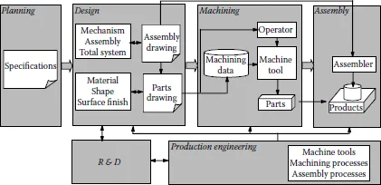
An example of a process flow in general manufacturing industry.
Figure 1.1 shows an example of a process flow, from specifications to products, in a general manufacturing industry. The manufacturing process can be divided into six stages based on function. They are planning, research and development (R&D), design, production engineering, machining, and assembly. Design, production engineering, machining, and assembly will be discussed in this chapter because an evaluation of technical skill is relatively easy in these processes.
1.1.1 Design
In design work, an assembly drawing, which gives an overview of the product, is created first. Next, a drawing of each and every part is produced, based on the assembly drawing. Once the assembly drawing and part drawings are approved, they are turned into work orders and handed over to the divisions that will use them. In days past, designers drew their ideas of three-dimensional (3D) products and parts on two-dimensional (2D) paper using writing materials and according to particular conventions and standards. It was a special skill of designers to copy ideas in 3D onto 2D paper and to reconstruct the information on 2D paper into 3D ideas. It was a skill that was much sought after.
Today, however, designs using computer-aided design (CAD) have become mainstream. It has become possible to create 3D parts virtually in a computer, directly from 3D data, and to combine them to create a virtual 3D product. Movement of and interference between the parts can be checked. If no problem is found, blueprints can be created automatically or data can be produced for processing purposes. Nowadays the old 3D-to-2D conversion skills are hardly needed. Yesterday’s drawing boards and paper are hardly seen in design departments, as the changeover to CAD is almost universal. However, at the same time, electrical controls are so frequently used for machine tools that design is often divided into electrical control design and structural design. Now, the ability to integrate these disciplines is much sought after.
1.1.2 Production Engineering
The production engineering part of the manufacturing process is not generally well understood by people outside manufacturing industry. The information on drawings from the design department is normally not sufficiently complete for the drawings to be passed directly to the processing and assembly sites. The information includes images of the completed parts and products, what materials and processing methods (for example milling, drilling) should be used, and dimensional and accuracy requirements. In order to complete the work according to the design drawing, it is necessary to decide in more detail on the procedures relating to manufacturing. For example, it must be decided which machine tools to use, how to hold parts in the tools during manufacture, in what order to make the different features, and when parts should be inspected during the manufacturing process, all taking cost into account. It must also be decided in what order to assemble the parts and, depending on the situation, whether it is more effective to make the part in-house or to order it from an outside supplier.
In the past, the design department would check all these. However, as the complexities and options in manufacturing have increased, now the design department creates the ideal image of the product. The details of manufacture and inspection are left to the experts. The production engineers in the production engineering department are those experts. Making a successful product depends much on this department.
1.1.3 Machining
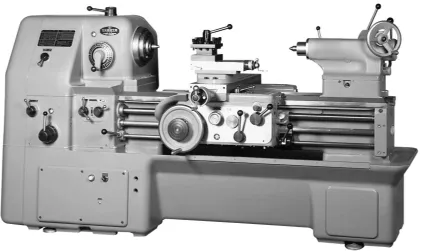
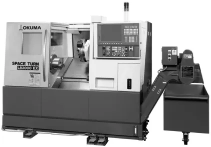
Machining is a processing department. Machine tools are either so-called manually controlled machine tools or numerically controlled (NC) tools. A manually controlled machine tool, as shown in Figure 1.2, is one that a worker controls manually by turning handles and levers to select cutting speeds and tool movements. Consequently, the quality of each part made in a manually controlled machine tool is directly affected by the worker’s skill. On the other hand, cutting speeds and tool movements of an NC machine tool, as shown in Figure 1.3, are controlled by servomotors. The actions of these are controlled by programs created in advance, called NC programs. Once a program is written, the machine tool can be used repeatedly to make many nominally identical parts. The worker’s skill becomes setting up and maintaining the machine tool’s actions.
FIGURE 1.2
A manual lathe. (From Okuma Corporation, model LS. With permission.)
1.1.4 Assembly
Assembly is the department where all the machined and other parts are brought together to be assembled. Assembly is divided into subassembly and general assembly. A machine tool (the subject of this example) may be considered to be made up of several components according to their functions. Each component itself has parts. The parts of each component are normally assembled first (subassembled) before general assembly. General assembly is the final process whereby subassembled components are built up. Adjustment and alignment are essential works for giving accuracy and quality assurance (QA) to the machine tool. In the assembly shop, various jigs are used. These are tools for holding parts in position. They play an auxiliary role in helping assembly to be carried out effectively. Furthermore, a process called scraping is done. This is part of the final adjustment for attaining best possible shape and mechanical accuracy of the assembly. Workers, using a hand tool called a scraper, scrape away small amounts of material from the surfaces of parts that are to be fixed together until the parts fit together with least possible distortion. Normally just a few micrometers in depth are scraped away. Scraping is described further in Chapter 4. It is a most difficult skill to learn.
FIGURE 1.3
A numerically controlled (NC) lathe. (From Okuma Corporation, model LB3000EX. With permission.)
1.2 INFORMATION AND OBJECT FLOWS IN MANUFACTURING
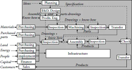
The stages of manufacturing a machine tool have been explained in outline in the previous section. The accompanying flow of information and materials (raw materials, parts, products) is shown in the block diagram of Figure 1.4. The solid lines show the flow of materials and the dashed lines show the flow of information. To explain the figure simply:
• Planning the purpose of a product, from an idea, is carried out first.
FIGURE 1.4
Information and materials flow in manufacturing.
• Design is then carried out based on the planning.
• The design is developed for manufacture in production engineering.
• Raw materials and parts are purchased and inspected.
• Raw materials are passed on to the machine shop to be processed according to machining information from production engineering.
• The machined parts are inspected and any defective ones are returned to the machine shop.
• Parts that have passed inspection are assembled in the assembly shop.
• Finished products are inspected and if a defective unit is found, readjustments are carried out.
• After inspection, the products are sold and sent to the customer.
• In addition, a department for preparing land and energy facilities as well as sufficient infrastructure is important for these actions to take place.
Although the overall information and materials flows are from upstream to downstream, from planning to assembly, they are not constantly in one direction. Parts are inspected along the way. If a fault is found, a part is returned to the point where the fault occurred and corrections are made. Or the cause of the fault is corrected. Such corrections may be considered to be the result of feedback. Finally, although the flows are shown as occurring sequentially in Figure 1.4, in reality all stages are occurring simultaneously, with different products at different stages of their manufacture.
1.3 COMPATIBLE MANUFACTURING METHODS
The mass-produced industrial products in our daily lives rely on compatible manufacturing methods for their production. Products consist of parts that need to be assembled. Compatible manufacturing methods are defined as ones that produce parts within the required dimensional range or precision for assembly. When out-of-range parts are excluded, it is guaranteed that there is no problem with assembly.
In manufacturing, it is important to understand that it is impossible to make a batch of parts exactly to the same size. This is true whatever the manufacturing process, whether it be a hand or a machine process. Although one cause is variability in the materials from which the parts are made, the greatest reason is that the thermal and mechanical conditions cannot be completely controlled when processing the materials into the required shape. For example, in machining work, tool wear is inevitable and causes the part size to differ from that required.
One way to cope with size variations is to carry forward all parts to the assembly stage and then make any small corrections needed for them to fit together. In that situation, every finished part may be different from every other. Also, it needs skill. There is a case from the 1800s (described in Samuel Lilley, Men, Machines and History, New York: International Publishers, 1966) in which 200,000 mass-produced muskets had faults and they could not be used because no one could fix them.
If this type of problem is avoided, by keeping size variations to within a range of approximately the same dimensions that leads to no faults on assembly, with no need for reprocessing or readjustment, then the time for assembly becomes much shorter. In addition, if a part of a product becomes broken, it is repairable by replacing only the broken part with a new part. And if repairs can be made only by exchanging parts, less skill is required. Based on this sort of reasoning, in the early 1800s the idea was born to determine what were the permissible size variations that did n...