![]()
1 | An Introduction to Networks |
Everyone knows what the Internet is, right? We all use it, we rely on it, and our society has almost become dependent on it. However, do we really understand what the Internet is and how it works? To many, the Internet is some nebulous entity. It is out there and we connect to it, and messages magically traverse it. In this textbook, we explore the Internet and its many components.
This is not just another network textbook. Network textbooks have existed for decades. Many of them describe in detail the hardware and protocols that make up networks. Some are specific to just one protocol, Transmission Control Protocol/Internet Protocol (TCP/IP). Others explore how to write programs that we use on the network. Yet other books describe how to secure your network from attacks. This textbook has taken a different approach in exploring the Internet. We will cover the basics (networks in general, hardware, and TCP/IP), but then, we will explore the significant protocols that we use to make the Internet work. Using several case studies, we will examine the most popular software that help support aspects of the Internet: TCP/IP tools, a Domain Name System (DNS) server, a Dynamic Host Configuration Protocol (DHCP) server, a web server, a proxy server, web caching, load balancing, and cloud computing software.
In this chapter, we will start with the basics. We will first explore network hardware and some of the more popular network protocols (excluding TCP/IP). We will also look at several network-related topics such as error detection and correction, encryption, and network caches. Most of this material (and TCP/IP, covered in Chapter 3) set the stage for the rest of the textbook. So, sit back, relax, and learn about one of the most significant technologies on the planet.
1.1 NETWORK COMMUNICATION
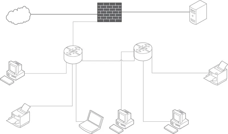
Let us start with some basics. A network is a group of connected things. A computer network is a collection of connected computer resources. These resources include but are not limited to computers of all types, network devices, devices such as printers and optical disc towers, MODEMs (MODEM stands for MOdulation DEModulation), the cable by which these resources are connected, and, of course, people. Most computers connected to a network are personal computers and laptops, but there are also servers, mainframe computers, and supercomputers. More recently, mobile devices such as smart phones and tablets have become part of computer networks. We can also include devices that are not general-purpose computers but still access networks, such as smart televisions (TVs), Global Positioning System (GPS) devices, sensors, and game consoles. Figure 1.1 illustrates a network of computers connected by two network devices. In the figure, there are numerous computers and a server (upper right-hand corner) as well as two printers connected to two routers, which connect the rest of these devices to the Internet with a firewall set between the network and the Internet. In Sections 1.1.1 through 1.1.4, we further define some of these terms.
FIGURE 1.1 Example computer network.
1.1.1 NETWORK DEVICES
A network device is a device that receives a message from one resource on a network and determines how to pass the message along the network. The network device might directly connect to the destination resource, or it may connect to another network device, in which case it forwards messages on to the next device. Common network devices are hubs, switches, routers, and gateways. These devices can be wired, wireless, or both.
The hub is the most primitive of the network devices. It operates by receiving a message and passing it on to all the resources it connects to. The hub is sometimes referred to as a multiport repeater, because its job is to repeat the incoming message across all its ports (connections). Note that this is not the same as a multicast, which we will discuss later in this section.
The hub also handles collision detection by forwarding a jam signal to all the connected devices, should multiple messages arrive at the same time. The jam signal indicates that a message collision occurred among the devices connected to it. When this happens, each device trying to communicate waits for a random amount of time before retrying to resend its message. Hubs are mostly obsolete today because of superior devices such as the network switch.
The network switch passes an incoming message onto a single resource. The switch uses the message’s destination address to determine the device to which the message should be passed. This address is known as a low-level address and is referred to as the hardware address or the media access control (MAC) address. The switch is also known as a MAC bridge.
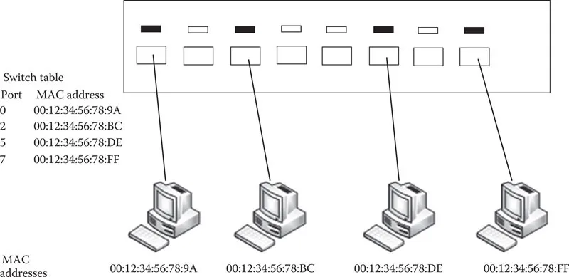
When a device is connected to a switch, the switch acquires that device’s MAC address and retains it in a table. This table is a simple listing that for each port on the switch, the attached device’s hardware address is stored. In Figure 1.2, we see a switch connecting four devices and the table that the switch maintains. Notice that since the switch has more than four ports, some of the port numbers are currently not used in the table.
On receiving a message, the switch examines the destination MAC address and forwards the message on to the corresponding port, as specified in its table. Some switches can also operate on network address (e.g., IP addresses). The main difference between a switch and a router is that the router operates on network addresses exclusively and not on hardware addresses. We will differentiate between types of switches later in this chapter.
The router operates at a higher level of the network protocol stack than the switch. The router utilizes the message’s destination network address to route the message on to its next step through the network. This network address is dependent on the type of network protocol. Assuming TCP/IP, the network address is an Internet Protocol version 4 (IPv4) or Internet Protocol version 6 (IPv6) address. The next step does not necessarily mean the destination device. Routers route messages across networks, so that they are forwarded on to the next point in the network that takes the message closer to its destination. This might be to the destination computer, to a network switch, or to another router. Routers therefore perform forwarding. A sample network routing table is shown in Table 1.1 (the content of the routing table, including terms such as netwmask and interface, is discussed later in this chapter). Metric is a cost of using the indicated route. This value is used by the router to determine the hop that the message should take next, as it moves across the network.
FIGURE 1.2 Network switch and its table.
TABLE 1.1
Sample Routing Table
Network Destination | Netmask | Gateway | Interface | Metric |
0.0.0.0 | 0.0.0.0 | 10.15.8.1 | 10.15.8.164 | 10 |
10.15.8.0 | 255.255.252.0 | On-link | 10.15.8.164 | 266 |
10.15.8.164 | 255.255.255.255 | On-link | 10.15.8.164 | 266 |
127.0.0.0 | 255.0.0.0 | 127.0.0.1 | 127.0.0.1 | 306 |
192.168.56.0 | 255.255.255.0 | 192.168.56.1 | 192.168.56.1 | 276 |
192.168.56.1 | 255.255.255.255 | 192.168.0.100 | 192.168.56.1 | 276 |
192.168.0.100 | 255.255.255.255 | 127.0.0.1 | 127.0.0.1 | 306 |
224.0.0.0 | 240.0.0.0 | On-link | 192.168.56.1 | 276 |
255.255.255.255 | 255.255.255.255 | On-link | 10.15.8.164 | 266 |
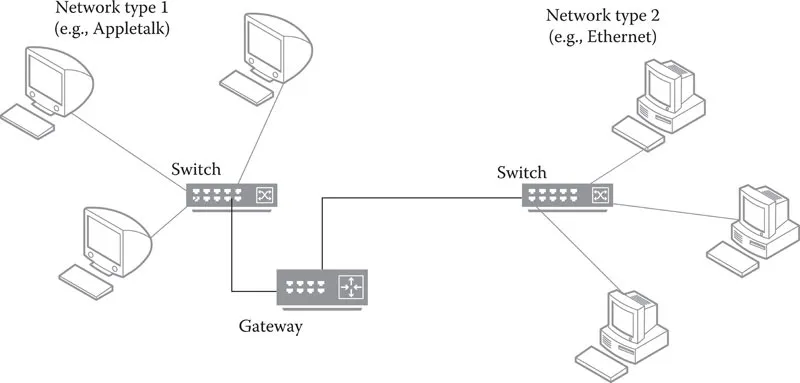
The gateway is a router that connects different types of networks together. More specifically, the gateway has the ability to translate a message from one protocol into another. This is handled by hardware or software that maps the message’s nondata content from the source network’s protocol to the destination network’s protocol. Figure 1.3 shows two different types of local area networks (LANs) connected by a gateway. The gateway is like a router, except that it is positioned at the edge of a network. Within a LAN, resources are connected by routers or switches. Routers and gateways connect LANs together. Oftentimes, a LAN’s connection to the Internet is made through a gateway rather than a router.
FIGURE 1.3 Positioning the gateway at the Edge of networks.
Note that the terms switch, router, and gateway are sometimes used interchangeably. For instance, switches that also utilize IP addresses are sometimes referred to as layer 3 switches, even though they are operating like routers. Routers are sometimes referred to as gateways whether they are translating protocols or not. As stated previously, we will visit protocols later in this chapter, and at that time, we will revisit the roles of the switches, routers, and gateways.
The typical form of communication over a network is a unicast. This form of communication allows a message to be sent from one source device to one destination device. The source and destination will typically open a communication channel (session) where communication may be one-directional or bi-directional (in which case, it is known as a duplex mode). However, there are times when communication is a one-to-many or many-to-many situation. This occurs when one or more devices are communicating with multiple devices. That is, there are multiple destination devices that a message is intended for. Such a communication is known as a multicast. A hub performs a limited form of multicast. A more specific reason for a multicast occurs when a server is streaming content to many destinations. Rather than duplicating the message at the server end, the message is sent out onto the network where routers are responsible not just for forwarding the content but also duplicating the content to be sent to multiple destinations. Another example for a multicast is with a multiplayer networked computer game. When one player performs an operation from within the software, all other players must see that move. The player’s computer does not have to duplicate messages to send to all other players. Instead, the routers take care of this by duplicating the message, resulting in a multicast.
Two other forms of communication are broadcast and anycast. A broadcast is a message sent from one device to all others on its local subnetwork (we define a subnet later in this chapter). The hub is a network broadcast device in that its job is to broadcast to all devices on its local network. Although this is like a multicast in that a message is duplicated, it is a multicast within a very limited setting. In other words, a multicast is a broadcast where destinations are not restricted to the local subnetwork. Finally, an anycast is somewhat of a compromise between a unicast and a multicast. With an anycast, there are several destinations that share the same IP address. A message is sent that could conceivably go to any of these destinations but is always routed to the nearest destination. In this way, an anycast will reach its destination in the shortest amount of time. We will refer to multicast, broadcast, and anycast from time to time through the text. If we do not explicitly mention the form of communication, assume that it is a unicast.
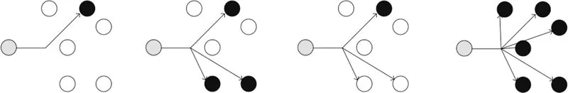
Figure 1.4 illustrates the difference between unicast, multicast, anycast, and broadcast. In this subnetwork, six devices are connected to our network device (a switch in this case). On the left, we have a unicast message, in which the switch sends the message to a single device. Next, we have a multicast, in which the switch sends the message to several specified devices. Then, we have anycast, in which the switch sends a message to all devices with the same IP address, but only one needs to receive it. Finally, on the right, the message is broadcast to all devices.
FIGURE 1.4 Comparing unicast, multicast, anycast, and broadcast.
1.1.2 SERVERS
The word server can...