Solve Complex Ground and Foundation Problems
Presenting more than 25 years of teaching and working experience in a wide variety of centrifuge testing, the author of Centrifuge Modelling for Civil Engineers fills a need for information about this field. This text covers all aspects of centrifuge modelling. Expertly explaining the basic principles, the book makes this technique accessible to practicing engineers and researchers.
Appeals to Non-Specialists and Specialists Alike
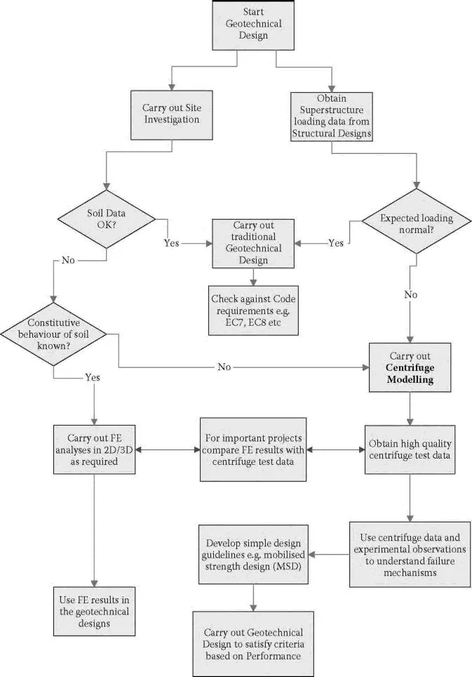
Civil engineers that are new to the industry can refer to this material to solve complex geotechnical problems. The book outlines a generalized design process employed for civil engineering projects. It begins with the basics, and then moves on to increasingly complex methods and applications including shallow foundations, retaining walls, pile foundations, tunnelling beneath existing pile foundations, and assessing the stability of buildings and their foundations following earthquake-induced soil liquefaction. It addresses the use of modern imaging technique, data acquisition, and modelling techniques. It explains the necessary signal processing tools that are used to decipher centrifuge test data, and introduces the reader to the specialist aspects of dynamic centrifuge modelling used to study dynamic problems such as blast, wind, or wave loading with emphasis on earthquake engineering including soil liquefaction problems.
- Introduces the equipment and instrumentation used in centrifuge testing
- Presents in detail signal processing techniques such as smoothing and filtering
- Provides example centrifuge data that can be used for sample analysis and interpretation
Centrifuge Modelling for Civil Engineers