![]()
Chapter 1
Introduction
Digital halftoning refers to the process of converting a continuous-tone image or photograph into a pattern of black and white picture elements (Fig. 1.1) for reproduction by a binary display device such as an ink jet printer, which can only choose to print or not print dots. The human visual, acting like a low-pass filter, blurs these printed and not printed dots together to create the illusion of continuous shades of gray. Depending on the specific manner in which dots are distributed, a given display device can produce varying degrees of image fidelity with more or less graininess. According to the human visual system, randomly arranged and isolated dots, properly distributed, should produce images with the highest quality, maintaining sharp edges and other fine details. But at the same time, certain display and printing devices are incapable of reproducing isolated dots consistently from dot to dot and, consequently, introduce printing artifacts that greatly degrade those same details that the dot distribution is designed to preserve. For this reason, many printing devices produce periodic patterns of clustered dots, which are easier to produce consistently across the printed page. So in studying halftoning, the principal goal is to determine what is the optimal distribution of dots for that device and then to produce these patterns in a computationally efficient manner.
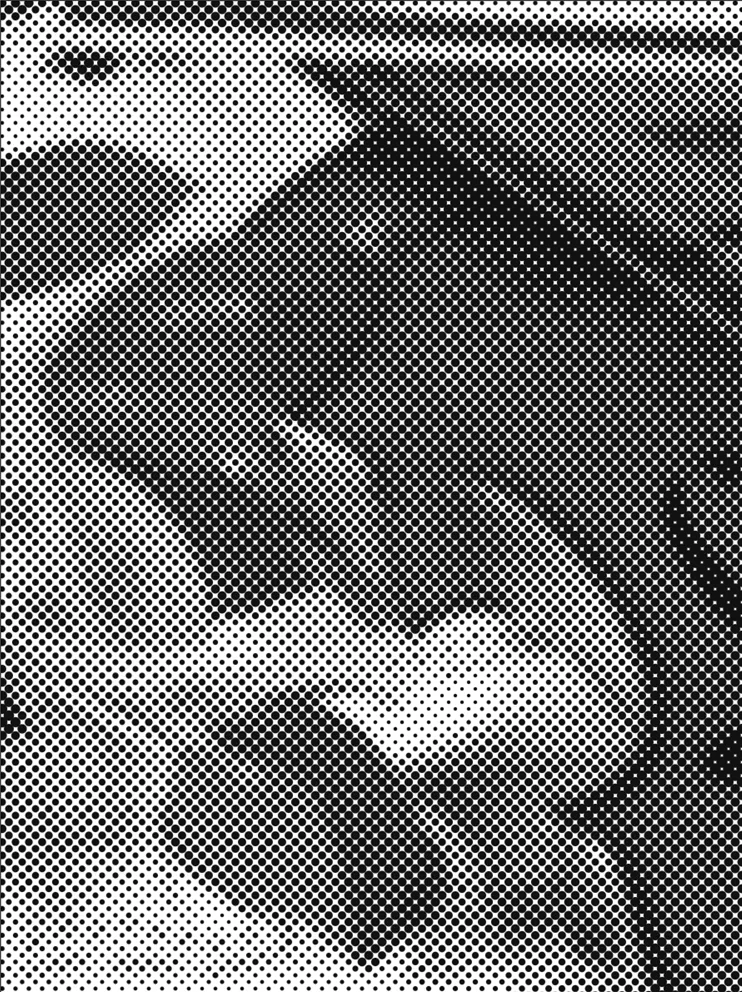
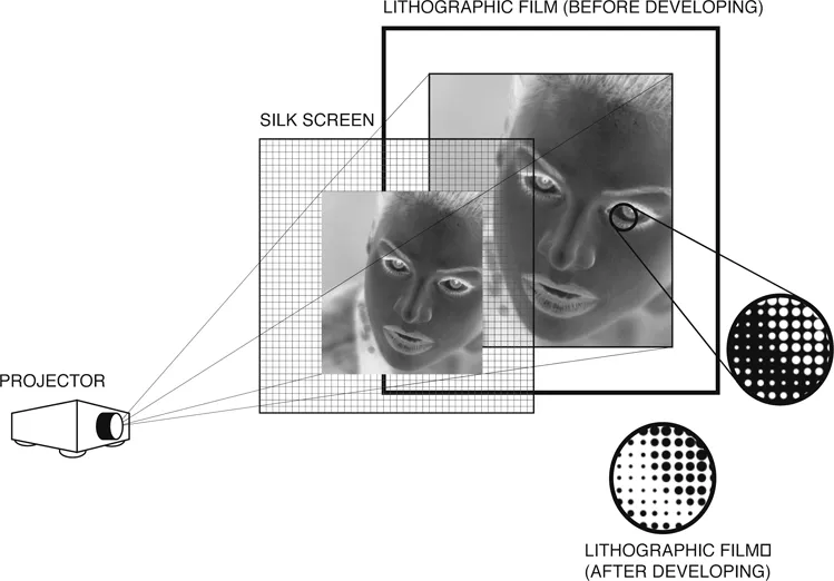
When analog halftoning was perfected in 1880, continuous-tone, monochrome photographs were reproduced as line drawings authored by highly skilled craftsmen, usually on scratch board. But with halftoning, newspapers and magazines could cheaply reproduce photographs in their publications, making photography a lucrative industry and resulting in a technical revolution in photographic equipment. In terms of photo-lithography, the early halftoning processes (Fig. 1.2) involved projecting light from the negative of a continuous-tone photograph through a mesh screen, such as finely woven silk, onto a photo-sensitive plate. Bright light, as it passes through a pin-hole opening in the silk screen, would form a large, round spot on the plate. Dim light would form a small spot. Light sensitive chemicals coating the plate would then form insoluble dots that varied in size according to the tones of the original photographs. After processing, the plate would have dots where ink was to be printed raised slightly above the rest of the plate.
Figure 1.1: Gray-scale image reproduced as an analog halftone.
Figure 1.2: The binary halftone obtained by projecting the negative of the original continuous-tone image through a fine silk screen.
Later versions of the halftoning process employed screens made of glass that were coated, on one side, by an opaque substance [116]. A mesh of parallel and equidistant lines were scratched in the opaque surface. A second mesh of parallel and equidistant lines were then scratched in the opaque surface running perpendicular to the original set. Screens would then differ in the number of lines per inch that had been scratched. While finer screens created better spatial resolutions (detail), the quality of the printing press would limit the fineness of the mesh.
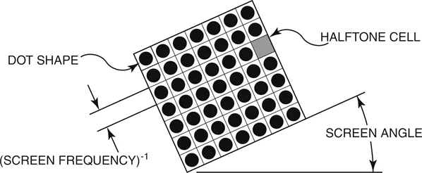
Later still, the glass plate mesh was replaced altogether with a flexible piece of processed film, placed directly in contact with the unexposed lithographic film [28]. This contact screen had direct control of the dot structure (Fig. 1.3) being able to control the screen frequency (the number of lines per inch), the dot shape (the shape of dots as they increase in size from light to dark), and the screen angle (the orientation of lines relative to the positive horizontal axis).
Figure 1.3: The screen frequency, dot shape, and screen angle for an analog halftone pattern.
1.1 AM Digital Halftoning
Today, printing is a far more advanced process with the introduction of non-impact printing technologies and the emergence of desktop publishing. Brought on by advancements in the digital computer [28], the photo-mechanical screening process introduced in 1880 has, in many instances, been replaced by digital imagesetters. In some instances, printing is no longer binary as continuous-tone dye-sublimation printers are now readily available but due to their speed and material requirements (special papers and inks), have not reached the wide-spread acceptance of color ink jet or electro-photographic (laser) printers, although dye-sublimation has made a major come back with a consumer market for 4 inch by 6 inch photograph printers.
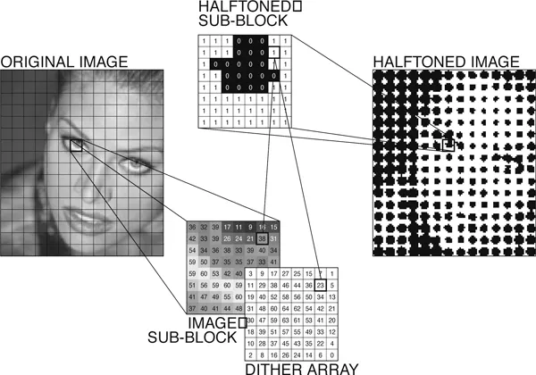
In these digital printers, the halftoning process of projecting a continuous-tone original through a halftone screen has been replaced with a raster image processor (RIP) that converts each pixel of the original image from an intermediate tone directly into a binary dot based upon a pixel-by-pixel comparison of the original image with an array of thresholds (Fig. 1.4). Pixels of the original with intensities greater than their corresponding threshold are turned “on” (printed) in the final halftoned image while pixels less than their corresponding thresholds are turned “off”. For large images, the threshold array is tiled end-to-end until all pixels of the original have a corresponding threshold.
Figure 1.4: Digital AM halftoning.
When first introduced, RIPs imitated the halftone patterns of contact screens by employing clustered-dot ordered dithering, where the threshold array is small (8 × 8, 12 × 12, or 16 × 16) and is composed of consecutive thresholds arranged along a spiral path radiating outward from the array’s center (Fig. 1.5). These arrangements of thresholds result in a single cluster of “on” pixels centered within each tile or cell, forming a regular grid of round dots that vary in size according to tone. These techniques are commonly referred to as amplitude modulated or AM digital halftoning due to their modulating of the size of printed dots. Like contact screens, the resulting patterns vary in their screen frequency, dot shape, and screen angle.
1.2 FM Digital Halftoning
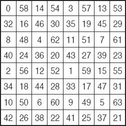
Due to freedoms afforded by digital printers, the idea of printing isolated pixels in an effort to minimize halftone visibility (the visibility of the individual dots to a human viewer) emerged as an alternative to clustered-dot dithering. By maintaining the size of printed dots for all gray-levels as individual pixels, new dispersed-dot halftoning techniques varied, according to tone, the spacing between printed dots, earning the name frequency modulated or FM halftoning. Early FM halftoning techniques were proposed by Bayer [11] and Bryngdahl [15] and produced an ordered arrangement of isolated dots. These techniques, like AM halftoning schemes, quantized each pixel independently of its neighbors (point process) according to a dither array but with consecutive thresholds dispersed as much as possible. The problem associated with these early FM techniques is that, as in the case of Bayer’s dither array (Fig. 1.6), resulting halftoned images (Fig. 1.7) suffered from a periodic structure that added an unnatural appearance [123].
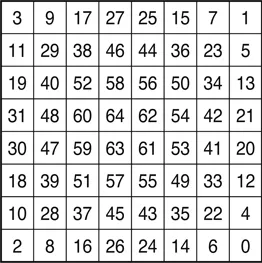
Figure 1.5: An 8 × 8 dither array (65 gray-levels).
For a far better approach to FM halftoning, Floyd and Steinberg [40] proposed the revolutionary error-diffusion algorithm (shown in Fig. 1.8 and covered in Chapter 5), an adaptive technique that quantized each pixel according to a statistical analysis of an input pixel and its neighbors (neighborhood process), leading to a stochastic arrangement of printed dots. While this neighborhood process had higher computational complexity, the resulting patterns had apparent spatial resolutions much higher than those achieved by clustered dots (Fig. 1.9); furthermore, as a stochastic patterning of dots, the patterns eliminated the occurrence of the moiré that was produced by the superimposing of two or more regular patterns.
By using FM halftoning schemes, printers maximize their apparent spatial resolution and are relieved of the strict tolerances on screen angles and screen registration. They can also use more and more colors to produce larger color gamuts (the set of achievable colors that can be produced by the printer) [76]. Notably, though, with its associated advantages, FM halftoning has, with few exceptions, only been employed in ink jet printers. The problem is the increased scrutiny placed on the printer’s ability to print small, isolated dots.
Figure 1.6: An 8 × 8 Bayer’s dither array (65 gray-levels).
Noting Fig. 1.10, the ideal display produces dots that completely cover the sample area associated with a given pixel without overlapping neighboring pixels’ sample areas. By printing all pixels, perfect black can be obtained. In a real printing device, individual printed dots are round and in order to produce perfect black, must be large enough as to cover the entire sample area (Fig. 1.11). By overlapping neighboring sample areas, though, the resulting tone is darker than the fraction of all pixels that are printed. Assuming that dots are printed consistently (small variation in size and shape from printed dot to printed dot), this distortion in tone can be corrected by adjusting the intensity level of the input image before halftoning. The amount of compensation depends on the arrangement of printed dots with dispersed-dot (FM) patterns requiring greater degrees of correction than clustered (AM). Ink jet printers are such a ...