- 693 pages
- English
- ePUB (mobile friendly)
- Available on iOS & Android
Electric Power Transformer Engineering
About this book
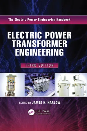
Electric Power Transformer Engineering, Third Edition expounds the latest information and developments to engineers who are familiar with basic principles and applications, perhaps including a hands-on working knowledge of power transformers. Targeting all from the merely curious to seasoned professionals and acknowledged experts, its content is structured to enable readers to easily access essential material in order to appreciate the many facets of an electric power transformer.
Topically structured in three parts, the book:
- Illustrates for electrical engineers the relevant theories and principles (concepts and mathematics) of power transformers
- Devotes complete chapters to each of 10 particular embodiments of power transformers, including power, distribution, phase-shifting, rectifier, dry-type, and instrument transformers, as well as step-voltage regulators, constant-voltage transformers, transformers for wind turbine generators and photovoltaic applications, and reactors
- Addresses 14 ancillary topics including insulation, bushings, load tap changers, thermal performance, testing, protection, audible sound, failure analysis, installation and maintenance and more
As with the other books in the series, this one supplies a high level of detail and, more importantly, a tutorial style of writing and use of photographs and graphics to help the reader understand the material. Important chapters have been retained from the second edition; most have been significantly expanded and updated for this third installment. Each chapter is replete with photographs, equations, and tabular data, and this edition includes a new chapter on transformers for use with wind turbine generators and distributed photovoltaic arrays. Jim Harlow and his esteemed group of contributors offer a glimpse into the enthusiastic community of power transformer engineers responsible for this outstanding and best-selling work.
A volume in the Electric Power Engineering Handbook, Third Edition.
Other volumes in the set:
- K12642 Electric Power Generation, Transmission, and Distribution, Third Edition (ISBN: 9781439856284)
- K12648 Power Systems, Third Edition (ISBN: 9781439856338)
- K13917 Power System Stability and Control, Third Edition (9781439883204)
- K12650 Electric Power Substations Engineering, Third Edition (9781439856383)
Watch James H. Harlow's talk about his book:
Part One: http://youtu.be/fZNe9L4cux0
Part Two: http://youtu.be/y9ULZ9IM0jE
Part Three: http://youtu.be/nqWMjK7Z_dg
Tools to learn more effectively

Saving Books

Keyword Search

Annotating Text

Listen to it instead
Information
1 Theory and Principles
- Magnetic Circuit
- Leakage Reactance
- Load Losses
- Short-Circuit Forces
- Thermal Considerations
- Voltage Considerations
1.1 Air Core Transformer


1.2 Iron or Steel Core Transformer


1.3 Equivalent Circuit of an Iron-Core Transformer
Table of contents
- Cover Page
- Half title
- Title page
- Copy right
- Preface
- Editor
- Contributors
- 1 Theory and Principles
- 2 Power Transformers
- 3 Distribution Transformers
- 5 Rectifier Transformers
- 6 Dry-Type Transformers
- 7 Instrument Transformers
- 8 Step-Voltage Regulators
- 9 Constant-Voltage Transformers
- 10 Transformers for Wind Turbine Generators and Photovoltaic Applications
- 11 Reactors
- 12 Insulating Media
- 13 Electrical Bushings
- 14 Tap Changers and Smart Intelligent Controls
- 15 Loading and Thermal Performance
- 16 Transformer Connections
- 17 Transformer Testing
- 18 Load-Tap-Change Control and Transformer Paralleling
- 19 Power Transformer Protection
- 20 Causes and Effects of Transformer Sound Levels
- 21 Transient-Voltage Response of Coils and Windings
- 22 Transformer Installation and Maintenance
- 23 Problem and Failure Investigation
- 24 On-Line Monitoring of Liquid-Immersed Transformers
- 25 U.S. Power Transformer Equipment Standards and Processes
- Index
Frequently asked questions
- Essential is ideal for learners and professionals who enjoy exploring a wide range of subjects. Access the Essential Library with 800,000+ trusted titles and best-sellers across business, personal growth, and the humanities. Includes unlimited reading time and Standard Read Aloud voice.
- Complete: Perfect for advanced learners and researchers needing full, unrestricted access. Unlock 1.4M+ books across hundreds of subjects, including academic and specialized titles. The Complete Plan also includes advanced features like Premium Read Aloud and Research Assistant.
Please note we cannot support devices running on iOS 13 and Android 7 or earlier. Learn more about using the app