1 Introduction
1.1 Historical perspective of offshore development
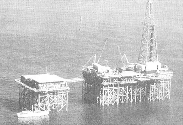
The first offshore oil rig ‘Superior’ was installed in 1947, 18 miles from the coast of Louisiana in the United States, in just 6 m depth of water (Figure 1.1). Today, there are over 7,000 offshore platforms around the world located in water depths now starting to exceed 2,000 m. As late as the early 1970s, deep-water developments meant water depths of 50–100 m, with the majority of platforms still in water depths of less than 50 m. Nowadays, the terms ‘deep water’ and ‘ultra-deep water’ are generally taken to refer to around 500 m and 1,500 m, respectively.
For many years, offshore design was dominated by the initial Gulf of Mexico experiences where soft clays dictated driven pile foundations, although soil conditions in the North Sea, Middle-East and (ultimately) the Southern Hemisphere (Australia, Brazil and West Africa) have each proved radically different, leading to new foundation approaches even for fixed platforms.
The Norwegian sector, aided by strong government policy to retain high Norwegian input, pioneered the development of concrete gravity structures in the North Sea, where stronger clays and dense sands provided adequate bearing capacity for shallow foundations.
Specific problematic soils (e.g. calcareous soils) or environmental conditions (e.g. ice forces in Canadian waters) led to new foundation or platform concepts (e.g. grouted piles in calcareous soils, sand islands in the Beaufort Sea).
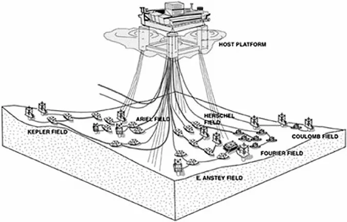
As hydrocarbon reserves close to continental landmasses have gradually been depleted, new fields have been developed at greater distances from land and, therefore, in deeper water. Development of fields in deep water has led to a variety of flexible structures (guyed towers) or floating facilities (tension-leg platforms and floating production units) tethered or moored by tension members and seabed anchors with perhaps the most significant being suction-installed deep caissons, such as those used for the Na Kika development (Figure 1.2, Newlin 2003a).
Greater distances separating the offshore development from land have necessitated either local storage, mainly for liquids, and periodic offloading onto tankers, or long export pipelines. There are also economic drivers to network adjacent fields, with pipelines bringing the product to a central facility for processing or export. These trends have led to much greater lengths of pipeline, both infield and for export, so that pipeline design has become an increasingly important economic factor in new developments.
Figure 1.1 Superior – The first offshore installation: 1947, Louisiana coast (from Leffler et al. 2003)
Figure 1.2 Na Kika development, Gulf of Mexico, 2,000 m water depth (Newlin 2003a)
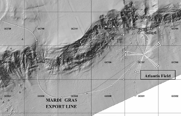
A further feature of developments in deep water is the increasing exposure to a range of geohazards, including dissociation of gas hydrates, migration of gas through the foundation soils, submarine slides emanating from the edge of the continental shelf and pipeline routing up steep and rugged terrain such as the Sigsbee escarpment in the Gulf of Mexico (Figure 1.3).
Figure 1.3 Sigsbee escarpment in the Gulf of Mexico (Jeanjean et al. 2005)
1.2 Features of offshore engineering
There a number of distinguishing features of geotechnical engineering for offshore conditions:
Site investigations are extremely expensive, with mobilisation and hire costs of suitable vessels typically several million US dollars.
Soil conditions are often unusual, particularly in respect of carbonate soils and corals.
Applied loads are large, with a high component of environmental loading, and large moment loading relative to the weight of the structure.
Design modifications during construction are generally not possible or incur severe cost penalties.
Emphasis is focused more on capacity, or ultimate limit state, than on deformations although the foundation stiffness is important for the dynamic response of the structure.
The cost of installing foundations, in combination with the relatively high environmental loads to be withstood, leads to large foundation sizes, such as piles of 2–3 m in diameter, penetrating up to 200 m below the seabed.
A typical field development may extend over a wide area (many tens of square kilometres), potentially with several fixed structures, or anchoring locations, and infield flowlines linking wells. Export pipelines, to shore or feeding into a regional trunkline, may also be required. Site investigation requirements may therefore extend over a significant region, even if limited to only shallow depths through most of it.
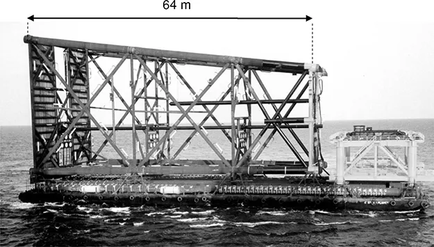
Figure 1.4 Moderate sized steel jacket structure during transport
It is convenient to divide offshore structures into fixed and floating structures, although a given foundation type may span both categories, e.g. piles used for a steel jacket structure, or as anchoring for tension-leg platforms or other types of floating systems. The evolving nature of foundation and anchoring systems to suit increasing water depths has necessitated considerable investment in research in order to validate new foundation and anchoring systems. In parallel, design guidelines or ‘Recommended Practices’ have been developed by the American Petroleum Institute (API) and, more recently, the International Standards Organisation (ISO). While these inevitably lag the advances in understanding achieved through research, industry has strived to keep pace by continuously updating the design codes through standing committees of specialists. Regulatory bodies such as the American Bureau of Shipping (ABS), Det Norske Veritas (DNV) and Lloyds, have also played an important role in validating new design approaches supported by research findings and helping to coordinate advances across the industry.
1.3 Foundations for fixed structures
The first offshore structures were a steel jacket, or template, design and soil conditions in the Gulf of Mexico comprising normally or lightly overconsolidated plastic clays dictated driven pile foundations. Initially, timber piles were used but were soon superseded by steel tubular piles for ease of construction. Simple platform designs incorporate the piles into the corners of the steel jacket (Figure 1.4), with the piles driven using either a steam hammer acting on a follower pile, or, in modern times, an underwater hydraulic hammer capable of fitting down the pile sleeves.
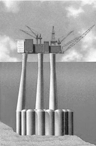
Typical soil conditions in the early development regions of the North Sea comprised heavily glaciated overconsolidated clays (with shear strengths generally 100– 700 kPa), interbedded with dense sands. These conditions permitted the development of concrete gravity structures, sitting directly on the seabed with minimal skirts. More recent platforms, such as Gullfaks C (Figure 1.5) and Troll, are in deeper water (200– 300 m) and with softer seabed conditions; this has necessitated much longer skirts, in the range 20–30 m, and the use of suction (technically reduced pressure compared with the ambient hydrostatic pressure) to help penetrate the skirts into the seabed.
Figure 1.5 Schematic of Gullfaks C concrete gravity structure
Steel-skirted foundations, variously referred to as plated or bucket foundations, or suction cans or caissons for individual elements, have proved to be an extremely versatile foundation approach, able to withstand compressive, tensile or lateral loading and to be installed using relatively lightweight support vessels. Suction caissons at the base of jacket structures have been used successfully as an alternative to gravity base structures in the North Sea.
Small structures can be based on simple tripod foundations (with a central tubular column supporting the deck) or a ‘monopod’ single pile. Hybrid structures (such as steel on a concrete base) are also becoming more common, as are less conventional approaches, for example, a mobile drilling (or ‘jack-up’) rig located more or less permanently on a steel or concrete mat foundation.
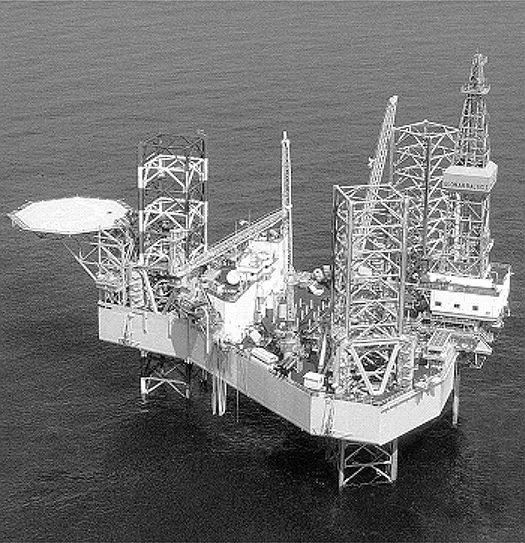
Jack-up units used as mobile drilling rigs (Figure 1.6) have three or four independent legs, each equipped with ‘spudcan’ foundations, which are shallow conical foundations with a central spigot on the underside. These may penetrate the seabed by several diameters as the hull of the unit is raised above the sea surface.
Piles, shallow foundations and spudcans are considered in detail in Chapters 5, 6 and 8, respectively.
1.4 Moorings for flexible and buoyant facilities
In deeper water, generally over 200 m, there is sufficient flexibility in conductor casing to allow relatively mobile or buoyant structures. At intermediate depths, up to perhaps 500 m, compliant towers (CTs) are a more attractive option than a conventional platform, for which the footprint would be very large. The CT operates with a large mass and buoyancy in the upper region giving a sluggish response to environmental loading. Typical 10–15-second-period waves pass through the structure before the structural frame can respond. Generally, CTs have a lower limit of around 300 m as in shallower waters the structure becomes too stiff to allow the concept to work.
Figure 1.6 Jack-up mobile drilling rig
Ronalds (2005) provides an overview of different types of floating systems, considering Floating Production Storage and Offloading vessels (FPSOs), semi-submersibles (semis), tension-leg platforms (TLPs – also mini-TLPs) and SPARs and the drivers behind choice of each system. All floating systems require moorings and ultimately, some form of anchor on the seabed.
Tension-leg platforms use vertical taut cables (or steel pipe) to apply tension between a seabed template and the buoyant facility. The seabed template ...