- 504 pages
- English
- ePUB (mobile friendly)
- Available on iOS & Android
eBook - ePub
The RF Transmission Systems Handbook
About this book
Although it is one of the oldest sectors of electronics and now somewhat taken for granted, radio frequency transmission literally changed our world. Today, it is still the backbone of myriad applications, from broadcasting to electronic counter-measures. The wide variety of hardware in use means that those working in the field must be familiar with a multitude of principles and applications, but finding an up-to-date, comprehensive source for this background material has been difficult, if not impossible.
The RF Transmission Systems Handbook addresses the underlying concepts, operation, and maintenance of high-power RF devices, transmission lines, and antennas for broadcast, scientific, and industrial use. Focusing on devices and systems that produce more than one kilowatt of output power, the handbook explores the following major topics:
Applications: The common uses of radio frequency energy
Fundamental principles: The basic technologies, concepts, and techniques used in RF transmission
Power vacuum devices: The principles and applications of gridded vacuum tubes and microwave power devices
Solid-state power devices: The operating parameters of semiconductor-based power devices
RF components and transmission lines: The operation of hardware used to combine and conduct RF power
Antenna systems: The different types of antennas and their basic operating parameters
Troubleshooting: Basic troubleshooting techniques and the operation of important test instruments
Contrary to the perceptions of many, RF technology remains a dynamic field that continues to advance to higher power levels and higher frequencies. Those who specify, install, and maintain RF equipment will welcome this reference that uniquely serves their needs.
Trusted by 375,005 students
Access to over 1.5 million titles for a fair monthly price.
Study more efficiently using our study tools.
Information
1
Applications of RF Technology
Jerry C. Whitaker
Editor
1.1 Introduction
Modulation Systems
Spread-Spectrum Systems
RF Power Amplifiers
Frequency Sources
Operating Class
Operating Efficiency
Broadband Amplifier Design
Amplifier Compensation
Stagger Tuning
Matching Circuits
Power Combining
Output Devices
1.2 Broadcast Applications of RF Technology
AM Radio Broadcasting
Shortwave Broadcasting
FM Radio Broadcasting
Television Broadcasting
1.3 Nonbroadcast Applications
Satellite Transmission
Radar
Electronic Navigation
Microwave Radio
Induction Heating
1.1 Introduction
Radio frequency (RF) power amplifiers are used in countless applications at tens of thousands of facilities around the world. The wide variety of applications, however, stem from a few basic concepts of conveying energy and information by means of a radio frequency signal. Furthermore, the devices used to produce RF energy have many similarities, regardless of the final application. Although radio and television broadcasting represent the most obvious use of high-power RF generators, numerous other common applications exist, including:
- Induction heating and process control systems
- Radio communications (two-way mobile radio base stations and cellular base stations)
- Amateur radio
- Radar (ground, air, and shipboard)
- Satellite communications
- Atomic science research
- Medical research, diagnosis, and treatment
Figure 1.1 illustrates the electromagnetic spectrum and major applications.
Modulation Systems
The primary purpose of most communications systems is to transfer information from one location to another. The message signals used in communication and control systems usually must be limited in frequency to provide for efficiency transfer. This frequency may range from a few hertz for control systems to a few megahertz for video signals. To facilitate efficient and controlled distribution of these signals, an encoder is generally required between the source and the transmission channel. The encoder acts to modulate the signal, producing at its output the modulated waveform. Modulation is a process whereby the characteristics of a wave (the carrier) are varied in accordance with a message signal, the modulating waveform. Frequency translation is usually a by-product of this process. Modulation can be continuous, where the modulated wave is always present, or pulsed, where no signal is present between pulses. There are a number of reasons for producing modulated waves, including:
- Frequency translation. The modulation process provides a vehicle to perform the necessary frequency translation required for distribution of information. An input signal can be translated to its assigned frequency band for transmission or radiation.
- Signal processing. It is often easier to amplify or process a signal in one frequency range as opposed to another.
- Antenna efficiency. Generally speaking, for an antenna to be efficient, it must be large compared with the signal wavelength. Frequency translation provided by modulation allows antenna gain and beamwidth to become part of the system design considerations. Use of higher frequencies permits antenna structures of reasonable size and cost.
- Bandwidth modification. The modulation process permits the bandwidth of the input signal to be increased or decreased as required by the application. Bandwidth reduction can permit more efficient use of the spectrum, at the cost of signal fidelity. Increased bandwidth, on the other hand, permits increased immunity to transmission channel disturbances.
- Signal multiplexing. In a given transmission system, it may be necessary or desirable to combine several different signals into one baseband waveform for distribution. Modulation provides the vehicle for such multiplexing. Various modulation schemes allow separate signals to be combined at the transmission end, and separated (demultiplexed) at the receiving end. Multiplexing can be accomplished using frequency-domain multiplexing (FDM) or time-domain multiplexing (TDM).
- Modulation of a signal does not come without undesirable characteristics. Bandwidth restriction or the addition of noise or other disturbances are the two primary problems faced by the transmission system designer.
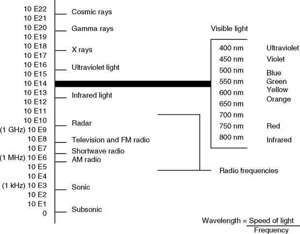
FIGURE 1.1 The electromagnetic spectrum.
Spread-Spectrum Systems
The specialized requirements of the military led to the development of spread-spectrum communications systems. As the name implies, such systems require a frequency range substantially greater than the basic information-bearing signal. Spread-spectrum systems have some or all of the following properties:
- Low interference to other communications systems
- Ability to reject high levels of external interference
- Immunity to jamming by hostile forces
- Provides for secure communications paths
- Operates over multiple RF paths
Spread-spectrum systems operate with an entirely different set of requirements than the transmission systems discussed previously. Conventional modulation methods are designed to provide for the easiest possible reception and demodulation of the transmitted intelligence. The goals of spread-spectrum systems, on the other hand, are secure and reliable communications that cannot be intercepted by unauthorized persons. The most common modulation and encoding techniques in spread-spectrum communications include:
- Frequency hopping, where a random or pseudorandom number (PN) sequence is used to change the carrier frequency of the transmitter. This approach has two basic variations: slow frequency hopping, where the hopping rate is smaller than the data rate; and fast frequency hopping, where the hopping rate is larger than the data rate. In a fast frequency hopping system, the transmission of a single piece of data occupies more than one frequency. Frequency hopping systems permit multiple-access capability to a given band of frequencies because each transmitted signal occupies only a fraction of the total transmitted bandwidth.
- Time hopping, where a PN sequence is used to switch the position of a message-carrying pulse within a series of frames.
- Message corruption, where a PN sequence is added to the message before modulation.
- Chirp spread spectrum, where linear frequency modulation of the main carrier is used to spread the transmitted spectrum. This technique is commonly used in radar and has also been applied to communications systems.
In a spread-spectrum system, the signal power is divided over a large bandwidth. The signal, therefore, has a small average power in any single narrowband slot. This means that a spread-spectrum system can share a given frequency band with one or more narrowband systems.
RF Power Amplifiers
The process of generating high-power RF signals has been refined over the years to an exact science. Advancements in devices and circuit design continue to be made each year, pushing ahead the barriers of efficiency and maximum operating frequency. Although different applications place unique demands on the RF design engineer, the fundamental concepts of RF amplification are applicable to virtually any system.
Frequency Sources
Every RF amplifier requires a stable frequency reference. At the heart of most systems is a quartz crystal. Quartz acts as a stable high Q mechanical resonator. Crystal resonators are available for operation at frequencies ranging from 1 kHz to 300 MHz and beyond.
The operating characteristics of a crystal are determined by the cut of the device from a bulk “mother” crystal. The behavior of the device strongly depends on the size and shape of the crystal and the angle of the cut. To provide for operation at a wide range of frequencies, different cuts, vibrating in one or more selected modes, are used.
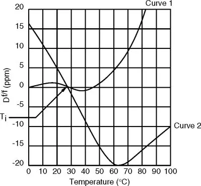
FIGURE 1.2 The effects of temperature on two types of AT-cut crystals.
Crystals are temperature sensitive, as shown in Fig. 1.2. The extent to which a device is affected by changes in temperature is determined by its cut and packaging. Crystals also exhibit changes in frequency with time. Such aging is caused by one or both of the following:
- Mass transfer to or from the resonator surface
- Stress relief within the device itself
Crystal aging is most pronounced when the device is new. As stress within the internal structure is relieved, the aging process slows.
The stability of a quartz crystal is inadequate for most commercial and industrial applications. Two common methods are used to provide the required long-term frequency stability:
- Oven-controlled crystal oscillator: a technique in which the crystal is installed in a temperature-controlled box. Because the temperature is constant in the box, controlled by a thermostat, the crystal remains on-frequency. The temperature of the enclosure is usually set to the turnover temperature of the crystal. (The turnover point is illustrated in Fig. 1.2.)
- Temperature-compensated crystal oscillator (TCXO): a technique where the frequency-vs.-temperature changes of the crystal are compensated by varying a load capacitor. A thermistor network is typically used to generate a correction voltage that feeds a varactor to re-tune the crystal to the desired on-frequency value.
Operating Class
Power amplifier (PA) stage operating efficiency is a key element in the design and application of an RF system. As the power level of an RF generator increases, the overall efficiency of the system becomes more important. Increased efficiency translates into lower operating costs and usually improved reliability of the system. The operating mode of the final stage, or stages, is the primary determining element in the maximum possible efficiency of the system.
All electron amplifying devices are classified by their individual class of operation. Four primary class divisions apply to RF generators:
- Class A: a mode wherein the power amplifying device is operated over its linear transfer characteristic. This mode provides the lowest waveform distortion, but also the lowest efficiency. The basic operating efficiency of a class A stage is 50%. Class A amplifiers exhibit low intermodulation distortion, making them well suited for linear RF amplifier applications.
- Class B: a mode wherein the power amplifying device is operated just outside its linear transfer characteristic. This mode provides improved efficiency at the expense of some waveform distortion. Class AB is a variation on class B operation. The transfer characteristic for an amplifying device operating in this mode is, predictably, between class A and class B.
- Clas...
Table of contents
- Cover Page
- Halftitle
- Title Page
- Copyright Page
- Preface
- Editor
- Contributors
- Contents
- 1 Applications of RF Technology
- 2 Electromagnetic Spectrum
- 3 Amplitude Modulation
- 4 Frequency Modulation
- 5 Pulse Modulation
- 6 Digital Modulation
- 7 High-Power Vacuum Devices
- 8 Microwave Vacuum Devices
- 9 Bipolar Junction and Junction Field-Effect Transistors
- 10 Metal-Oxide-Semiconductor Field-Effect Transistor
- 11 Solid-State Amplifiers
- 12 Coaxial Transmission Lines
- 13 Waveguide
- 14 RF Combiner and Diplexer Systems
- 15 Radio Wave Propagation
- 16 Antenna Principles
- 17 Practical Antenna Systems
- 18 Preventing RF System Failures
- 19 Troubleshooting RF Equipment
- 20 RF Voltage and Power Measurement
- 21 Spectrum Analysis
- 22 Testing Coaxial Transmission Line
- 23 Safety Issues for RF Systems
- Index
Frequently asked questions
Yes, you can cancel anytime from the Subscription tab in your account settings on the Perlego website. Your subscription will stay active until the end of your current billing period. Learn how to cancel your subscription
No, books cannot be downloaded as external files, such as PDFs, for use outside of Perlego. However, you can download books within the Perlego app for offline reading on mobile or tablet. Learn how to download books offline
Perlego offers two plans: Essential and Complete
- Essential is ideal for learners and professionals who enjoy exploring a wide range of subjects. Access the Essential Library with 800,000+ trusted titles and best-sellers across business, personal growth, and the humanities. Includes unlimited reading time and Standard Read Aloud voice.
- Complete: Perfect for advanced learners and researchers needing full, unrestricted access. Unlock 1.5M+ books across hundreds of subjects, including academic and specialized titles. The Complete Plan also includes advanced features like Premium Read Aloud and Research Assistant.
We are an online textbook subscription service, where you can get access to an entire online library for less than the price of a single book per month. With over 1.5 million books across 990+ topics, we’ve got you covered! Learn about our mission
Look out for the read-aloud symbol on your next book to see if you can listen to it. The read-aloud tool reads text aloud for you, highlighting the text as it is being read. You can pause it, speed it up and slow it down. Learn more about Read Aloud
Yes! You can use the Perlego app on both iOS and Android devices to read anytime, anywhere — even offline. Perfect for commutes or when you’re on the go.
Please note we cannot support devices running on iOS 13 and Android 7 or earlier. Learn more about using the app
Please note we cannot support devices running on iOS 13 and Android 7 or earlier. Learn more about using the app
Yes, you can access The RF Transmission Systems Handbook by Jerry C. Whitaker in PDF and/or ePUB format, as well as other popular books in Technology & Engineering & Electrical Engineering & Telecommunications. We have over 1.5 million books available in our catalogue for you to explore.