![]()
1
Reading Construction Drawings
1.1 Introduction
Construction drawings are necessary in most spheres of the building industry, as being the best means of conveying detailed and often complex information from the designer to all those concerned with the job. Building tradespeople, especially carpenters and joiners, should be familiar with the basic principles involved in understanding and reading drawings correctly. Mistakes on either side – in design or interpretation of the design – can be costly, as drawings form a legal part of the contract between architect/client and builder. This applies even on small jobs, where only goodwill may suffer; for this reason, if a non-contractual drawing or sketch is supplied, it should be kept for a period of time after completion of the job, in case any queries should arise.
1.1.1 Retention of Drawings or Sketches
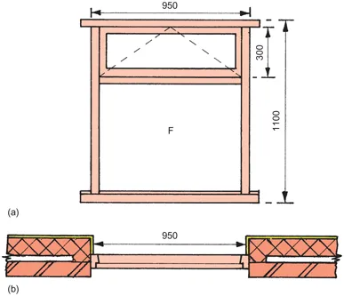
A simple sketch supplied by a client in good faith to a builder or joinery shop for the production of a replacement casement-type window, is shown in Figure 1.1(a). The client’s mistake in measuring between plastered reveals is illustrated in Figure 1.1(b). Retention of the sketch protects the firm from the possibility of the client’s wrongful accusation.
Another important rule is to study the whole drawing carefully and be reasonably familiar with the details before starting work.
The details given in this chapter are based on the recommendations laid down by the British Standards Institution, in their latest available publications entitled Construction drawing practice, BS 1192:
Part 1: 1984, and BS 1192: Part 3: 1987. BS 1192: Part 5: 1990, which is not referred to here, is a guide for the structuring of computer graphic information.
1.1.2 Scales Used on Drawings
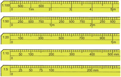
Parts of metric scale rules, graduated in millimetres, are illustrated in Figure 1.2. Each scale represents a ratio of given units (millimetres) to one unit (one millimetre).
Common scales are 1:100, 1:50, 1:20, 1:10, 1:5 and 1:1 (full size). For example, scale 1:5 = one-fifth (j) full size, or 1 mm on the drawing equals 5 mm in reality.
Although a scale rule is useful when reading drawings, because of the dimensional instability of paper, preference should always be given to written dimensions found on the drawing.
1.1.3 Correct Expressions of Dimensions
The abbreviated expression, or unit symbol, for metres is a lower case (small) letter m, and letters mm for millimetres. Symbols are not finalized by a full stop and do not use a letter ‘s’ for the plural. Confusion occurs when, for example, 3| metres is written as 3.500 mm – which means, by virtue of the decimal point in relation to the unit symbol, 3 2 1 millimetres! To express 3 1 2 metres, it should have been written as 3500 mm, 3.5 m, 3.50 m, or 3.500 m. Either one symbol or the other should be used throughout on drawings; they should not be mixed. Normally, whole numbers should indicate millimetres, and decimalized numbers, to three places of decimals, should indicate metres. Contrary to what seems to be taught in schools, the construction and engineering industry in the UK does not communicate in centimetres. All references to measurement are made in millimetres and/or metres, i.e. 2 cm should be expressed as 20 mm.
1.1.4 Sequence of Dimensioning
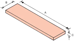
The recommended dimensioning sequence is illustrated in Figure 1.3. Length should always be given first, width second and thickness third, for example 900 × 200 × 25 mm. However, if a different sequence is used, it should be consistent throughout.
1.1.5 Dimension Lines and Figures
A dimension line with open arrowheads for basic/ mo...