- 244 pages
- English
- ePUB (mobile friendly)
- Available on iOS & Android
eBook - ePub
Practical Analog Electronics for Technicians
About this book
'Practical Analog Electronics for Technicians' not only provides an accessible introduction to electronics, but also supplies all the problems and practical activities needed to gain hands-on knowledge and experience. This emphasis on practice is surprisingly unusual in electronics texts, and has already gained Will Kimber popularity through the companion volume, 'Practical Digital Electronics for Technicians'.
Written to cover the Advanced GNVQ optional unit in electronics, this book is also ideal for BTEC National, A-level electronics and City & Guilds courses. Together with 'Practical Digital Electronics for Technicians', this text comprises a complete practical electronics course designed for students with little prior knowledge of the subject.
Trusted by 375,005 students
Access to over 1.5 million titles for a fair monthly price.
Study more efficiently using our study tools.
Information

Introduction
For those electrical engineers who did their initial training before digital electronics made such an impact, the analog way was the way of electrical life. Quite simply, that’s all there was for a while. Digital electronics, although not unknown, did not become an economic proposition until the advent of the integrated circuit in the 1960s. A question asking ‘what is analog all about?’ hardly seemed relevant.
Let us ask the question now. Just what is analog electronics and what place does it have in today’s world? A dictionary definition is perhaps only moderately helpful. We see for example, that The Concise Oxford Dictionary gives
analog (or analogue) as ‘a parallel word or thing’
analogous as ‘similar or parallel to’
analogy as ‘similarity’.
The more important aspect from our point of view, is the understanding of what an analog signal is and how it differs from the digital signal.
Digital and analog signals
The digital process recognizes a limited number of states or levels. The two-state logic system for example, is represented variously, by
on and off, 1 and 0, high and low
An example of a digital signal is shown in Figure 1.1.
The analog process, on the other hand, recognizes a continuously variable state, where the levels are, theoretically at least, infinitely variable between a lower and an upper limit. An example of an analog signal is shown in Figure 1.2.
A recognizable example is the speedometer in a car, in which the pointer can take any position between zero miles per hour and the maximum possible (or maximum allowed). The analog or analogy here, is the position of the pointer representing the quantity, speed. And of more immediate relevance, there is the moving coil meter, the pointer of which moves to a position related to the current through the coil. It is the presence of an indicator, such as the pointer, that helps the identification of an analog system.
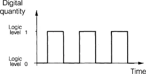
Figure 1.1 The digital signal

Figure 1.2 The analog signal
As far as the place for analog electronics in today’s world is concerned, it can be mentioned that most of the natural things we measure, such as temperature, wind speed, the human voice, vibrations (or oscillations, for which see Chapter 7), are all analog systems.
Referring again to pre-integrated circuit days, the only way of processing these systems was with analog circuits, of which amplification was one example.
With today’s technology it is frequently the case of converting an analog signal into a digital format and converting back again where necessary. There are many advantages in this technique which cannot be dealt with here.
The practical exercises
Typical equipment and the components needed are listed for each practical exercise.
The power supply voltages chosen for these exercises are those that, in the absence of a commercial unit, can be made up from easily available fixed and variable voltage regulators. The details for this are readily available in a variety of texts.
It will be seen that a dual-polarity (±V) supply is needed for the operational amplifier circuits. The requirement here is to provide both a positive and a negative voltage with respect to the 0 V line. This can, if necessary, be achieved with two single-polarity supplies as shown in Figure 1.3.
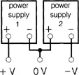
Figure 1.3 A dual power supply from two single power supplies
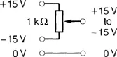
Figure 1.4 A single power supply from a dual power supply
For the exercises that need a supply voltage, variable from +V through zero to -V, this can be obtained by the method shown in Figure 1.4.
Waveform observation is always important, not least in fault finding, where even the absence of a signal can be revealing. A cathode ray oscilloscope (CRO) is essential, and preferably double beam, especially when phase shift details are needed. For the majority of the exercises the CRO has not been shown on the circuit diagram, but its general purpose is to display both the input and the output waveforms.
The audio frequency signal generator will need to provide a sinusoidal input signal to the unit, at modest voltage levels, up to a frequency of approximately 50 kHz. Most commercial units will do this in spite of this frequency being well outside the accepted audio frequency range. In addition, a square waveform at 10 V is required for one practical exercise.
The actual meter used for DC voltage and current measurements can be a personal choice of the user for the majority of the practical exercises. It would be more helpful to use the digital type wherever the need to avoid circuit loading is paramount (see Chapter 8). For fault finding in particular, the use of a digital voltmeter, when attempting to prove the existence of a short circuit, can overcome any difficulty in determining the precise reading on an analog meter. For a brief comparison between digital and analog meters, the reader is referred again to Chapter 8.
The manner of assembly of a particular circuit is, of course, a matter of choice for the practitioner. It is believed that the learning experience can be enhanced by a certain amount of self-assembly within the constraints of the time available. With this in mind, there are breadboard systems available where component wires push into holes on a 0.1 inch grid. Although this system is mostly convenient, it can, on occasions, also be the source of much frustration and despair!
A final word concerning the ‘batting order’ for the chapters. The natural order can be followed with safety, since it provides a natural progression of knowledge obtained through the chapters. The exception would be Chapter 8 – Test and measuring equipment – which can be taken at any stage, even first, if desired.

Although the use of thermionic valves may be making a comeback in some quarters, the great attraction of transistors and integrated circuits in, for example, personal stereos and other low-output power equipment, is the ‘carry everywhere’ aspect, which is in no small measure due to the low-voltage, low-power supply that the equipment requires.
As most users will know, this power supply can easily be provided by batteries, with the cost aspect considered by the use of rechargeable batteries. The wisdom of using a mains adaptor to reduce running costs to a minimum is advocated, although of course, portability is reduced.
For higher output powers, as offered by domestic high fidelity equipment, the use of batteries is not an economic pr...
Table of contents
- Cover
- Title page
- Copyright page
- Contents
- Preface
- List of practical exercises
- Chapter 1 Setting the scene
- Chapter 2 DC power supply units
- Chapter 3 Small signal amplifiers
- Chapter 4 Logarithmic units
- Chapter 5 Feedback
- Chapter 6 Operational amplifiers
- Chapter 7 Oscillators
- Chapter 8 Test and measuring equipment
- Chapter 9 Fault finding
- Answers to questions
- Index
Frequently asked questions
Yes, you can cancel anytime from the Subscription tab in your account settings on the Perlego website. Your subscription will stay active until the end of your current billing period. Learn how to cancel your subscription
No, books cannot be downloaded as external files, such as PDFs, for use outside of Perlego. However, you can download books within the Perlego app for offline reading on mobile or tablet. Learn how to download books offline
Perlego offers two plans: Essential and Complete
- Essential is ideal for learners and professionals who enjoy exploring a wide range of subjects. Access the Essential Library with 800,000+ trusted titles and best-sellers across business, personal growth, and the humanities. Includes unlimited reading time and Standard Read Aloud voice.
- Complete: Perfect for advanced learners and researchers needing full, unrestricted access. Unlock 1.5M+ books across hundreds of subjects, including academic and specialized titles. The Complete Plan also includes advanced features like Premium Read Aloud and Research Assistant.
We are an online textbook subscription service, where you can get access to an entire online library for less than the price of a single book per month. With over 1.5 million books across 990+ topics, we’ve got you covered! Learn about our mission
Look out for the read-aloud symbol on your next book to see if you can listen to it. The read-aloud tool reads text aloud for you, highlighting the text as it is being read. You can pause it, speed it up and slow it down. Learn more about Read Aloud
Yes! You can use the Perlego app on both iOS and Android devices to read anytime, anywhere — even offline. Perfect for commutes or when you’re on the go.
Please note we cannot support devices running on iOS 13 and Android 7 or earlier. Learn more about using the app
Please note we cannot support devices running on iOS 13 and Android 7 or earlier. Learn more about using the app
Yes, you can access Practical Analog Electronics for Technicians by W A Kimber in PDF and/or ePUB format, as well as other popular books in Technology & Engineering & Civil Engineering. We have over 1.5 million books available in our catalogue for you to explore.