- 584 pages
- English
- ePUB (mobile friendly)
- Available on iOS & Android
eBook - ePub
Chemical Grouting And Soil Stabilization, Revised And Expanded
About this book
Following shifting trends from remedial to preventive uses of grouting practices, this third edition covers all aspects of chemical grouting methods and applications. This reference highlights new ground improvement techniques as well as recent innovations in soil modification and stabilization procedures. It considers commercial alternatives to ground improvement, their relative advantages and disadvantages, and the engineering applications to which these methods are suited. Revised and expanded, this new edition assesses the role of new grouting techniques in the containment of hazardous waste and introduces numerous problems to illustrate concepts and facilitate instruction.
Trusted by 375,005 students
Access to over 1 million titles for a fair monthly price.
Study more efficiently using our study tools.
Information
1
Introduction
1.1 GENERAL
Under the action of gravity, surface water and groundwater always tend to flow from higher to lower elevations. Surface water will flow over solid and through permeable formations, and its volume and velocity are a function of the available supply and the fluid head. Groundwater can move only through a pervious material (fractured or fissured rock or soils with interconnected open voids), so its flow characteristic is also a function of formation permeability. Groundwater elevation varies as the supply source varies and can be raised or lowered locally by increasing or decreasing the local supply (naturally by precipitation or artificially by pumping a well or irrigating). In general, over a large surface area, groundwater surface is a subdued replica of ground surface.
Many construction projects require the lowering of the natural land surface to provide for foundations, basements, and other low level facilities. Other projects such as tunnels and shafts require underground construction of long, open tubes. Whenever such excavations go below groundwater surface, they disrupt the existing flow patterns by creating a zone of low pressure potential. Groundwater begins to flow radially toward and into the excavation. The situation is further aggravated by the fact that construction procedures generally enlarge existing fissures and voids and create new ones in the vicinity of the excavation.
Contractors anticipate infiltration when the excavation is planned to go below groundwater level and generally make provisions for diverting the flow of water before it reaches the excavation or removing it before or after it enters. Water problems during construction, which carry a cost penalty, occur when the provisions to handle groundwater prove ineffective. Water problems can range from nuisance value to actual retardation of the construction schedule to complete shutdown.
Water problems may also occur after the completion of construction. Seepage that may have been tolerable during construction may become intolerable during facility operations. Post construction seepage may increase to intolerable levels due to termination of construction seepage control procedures. Unanticipated water problems may occur because the structural elements cause long-term modification of surface drainage patterns or subsurface seepage patterns. Unusual amounts of precipitation may raise normal ground water levels. Occasionally, shrinkage cracks in, and settlement of foundation elements may result in postconstruction seepage problems.
The presence of unanticipated groundwater (either static or flowing) may lower the design value of bearing capacity. If higher values are used, based on dry conditions, water must be kept permanently from the foundation area. The presence of water in basement areas may prevent use of such areas.
The contractor has at his or her disposal many field procedures to prevent seepage or to control it after it reaches intolerable amounts. Some of these procedures are briefly discussed in Sec. 1.2.
1.2 MODIFICATION AND STABILIZATION
“Modification” implies a minor change in the properties of soil or rock, while “stabilization” implies any change which renders the soil or rock adequate for changed strength or permeability properties (or both) required by field construction. Generally, all modification procedures result in increased stability for granular materials and most cohesive soils, but not necessarily for rock formations. These terms are used interchangeably in this text.
For granular (non-cohesive) materials, modification always consists of changing the volume of the soil voids, or replacing the void material, or both. For cohesive materials, modification consists of mixing with stabilizers and preloading to eliminate or reduce future settlements.
Decreasing the void volume of a soil mass, when done slowly enough to avoid pore pressure build-up, results in increased shear strength, which increases bearing capacity and safety factor against plane failure. Replacing the void fluid with a solid material will decrease the formation permeability, and may also add shear strength. (Under some special conditions, replacing pore water with a weak grout may decrease the formation shear strength).
Field procedures to decrease the void volume include static and dynamic compaction, pile driving and the use of surface and deep vibratory equipment. Explosives have also been used for this purpose.
Ground water can be removed from a site by drainage ditches, by pumping from sumps, and by wellpoints and wells.
Field methods to replace or modify the void fluid include grouting (both particulate and chemical), freezing, surface and deep mixing, jet piling and slurry trenching. Compressed air may also be considered as a method of changing the void fluid from water to air.
This past decade has also seen the development of biological stabilization methods, which add strength to a soil mass through the growth of roots.
1.3 SOIL AND ROCK SAMPLING
Everything we build, at some point during its construction, rests on soil or rock. It is obvious that the soil or rock, for every specific case, must have adequate properties to support whatever rests on it without structural failure or deleterious settlement.
It is usually a straightforward design problem to determine the loads a structure’s foundation transmits to its supporting soil or rock. It is also a relatively straightforward problem to estimate the ability of the soil or rock to withstand the foundation loads. However, while the foundation loads can be determined to a high degree of accuracy, the estimation of soil and rock properties which determine bearing capacity is subject to many sources of error.
While a full-scale field loading test, properly performed and interpreted, will reliably define the foundation: soil interaction, such tests are generally not feasible. Thus, the way a soil or rock mass responds to being stressed is usually determined by previous experience in similar conditions, by extrapolating the results of small load tests or by using specific soil properties in various empirical formulae. These soil properties are sometimes inferred from previous experience, but more often reflect the results of laboratory and field tests on soil and rock samples.
Samples of soil from shallow depths can be obtained from holes or pits. In granular soils, holes and pits will cave unless the side slopes are less than 35 to 45 degrees. Therefore, taking samples in holes or pits becomes economically unfeasible below depths of several feet.
In cohesive soils, walls of a pit may remain vertical for considerable depth. However, below 5 to 6 feet personnel safety calls for bracing, making deep pits uneconomical.
Samples scraped from the sides or bottom of holes and pits are “disturbed”. That is, whatever structure and stratification the soil may have had in nature has been destroyed by the sampling operation.
Hand augers of all kinds can be used to extract soil samples from holes up to 20 feet and more. Motor driven augers can go much deeper. All such samples are disturbed, and may even be mixed from different strata.
The usual method for obtaining samples at significant depths below the surface is to push or drive a pipe or tube into undisturbed soil at the bottom of a drill hole. Of course, this process disturbs the soil, particularly when the pipe is heavy walled. Many different kinds and sizes of samplers are used, and the most common is shown in Figure 1.1. This sampler is commonly called a split spoon. When used with the dimensions shown, and hammered into the soil by a free falling, 140 pound weight, dropping 30 inches, this is the Standard Penetration Test (see ASTM Standard D.1586, Standard Method for Penetration and Split Barrel Sampling of Soils). The number of blows recorded per foot of penetration is used as a guide to other soil properties. Of course, the samples obtained are disturbed.
The degree of disturbance caused by driving a sampling spoon decreases as the spoon wall thickness decreases. The thinner the wall thickness, however, the more tendency for the spoon to crumple under the driving forces. For sampling granular soils, spoon wall thickness is generally 1/4 inch or more. For cohesive soils, tubing with walls as thin as 1/16 inch is often used. Sampling spoons using such tubing are known as Shelby Tube or Thin Wall Samplers. A typical design is shown in Figure 1.2 (see ASTM Standard D-1587, Standard Practice for Thin-Walled Tube Geotechnical Sampling of Soils).
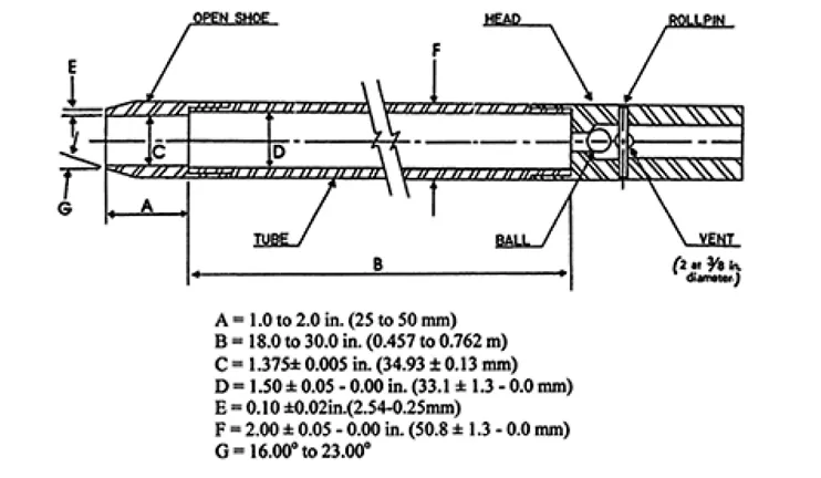
FIGURE 1.1 Split spoon sampler. (Reprinted with permission from The Annual Book of ASTM Standards, copyright ASTM, 100 Bar Harbour Drive, West Conshohocken, PA, 19428.)
Thin wall samplers are generally pushed into the soil rather than driven. Even so, they still cause disturbance mostly adjacent to the tube walls. If the outer 1/4 to 1/2 inch is discarded, what remains is c...
Table of contents
- Cover
- Half Title
- Series Page
- Title Page
- Copyright Page
- Contents
- Preface to the Third Edition
- Preface to the Second Edition
- Preface to the First Edition
- Acknowledgments
- 1. Introduction
- 2. Soil and Rock Properties
- 3. Compaction
- 4. Water Removal and Wellpointing
- 5. Ground Freezing
- 6. Piling, Nailing, and Mixing
- 7. Slurry Walls and Trenches
- 8. Biostabilization
- 9. Grouting with Cement
- 10. Chemical Grouts
- 11. Commercial Chemical Grouts
- 12. Grouting Theory
- 13. Grouting Technology
- 14. Field Equipment
- 15. Field Procedures and Tests
- 16. Grouting to Shut off Seepage
- 17. Grout Curtains
- 18. Grouting for Strength
- 19. Grouting in Tunnels and Shafts
- 20. Special Applications of Chemical Grouts
- 21. Specifications, Supervision, and Inspection
- 22. Containment of Hazardous Wastes
- Appendix A: Glossary of Selected Terms
- Appendix B: Computer Program for Optimal Grout Hole Spacing for a Chemical Grout Curtain
- Appendix C: Suggested Test Method for Determining Strength of Grouted Soils for Design Purposes
- Appendix D: Tunnel Design Criteria
- Appendix E: Field Research with Sodium Silicate
- Appendix F: Ground Improvement
- Index
Frequently asked questions
Yes, you can cancel anytime from the Subscription tab in your account settings on the Perlego website. Your subscription will stay active until the end of your current billing period. Learn how to cancel your subscription
No, books cannot be downloaded as external files, such as PDFs, for use outside of Perlego. However, you can download books within the Perlego app for offline reading on mobile or tablet. Learn how to download books offline
Perlego offers two plans: Essential and Complete
- Essential is ideal for learners and professionals who enjoy exploring a wide range of subjects. Access the Essential Library with 800,000+ trusted titles and best-sellers across business, personal growth, and the humanities. Includes unlimited reading time and Standard Read Aloud voice.
- Complete: Perfect for advanced learners and researchers needing full, unrestricted access. Unlock 1.4M+ books across hundreds of subjects, including academic and specialized titles. The Complete Plan also includes advanced features like Premium Read Aloud and Research Assistant.
We are an online textbook subscription service, where you can get access to an entire online library for less than the price of a single book per month. With over 1 million books across 990+ topics, we’ve got you covered! Learn about our mission
Look out for the read-aloud symbol on your next book to see if you can listen to it. The read-aloud tool reads text aloud for you, highlighting the text as it is being read. You can pause it, speed it up and slow it down. Learn more about Read Aloud
Yes! You can use the Perlego app on both iOS and Android devices to read anytime, anywhere — even offline. Perfect for commutes or when you’re on the go.
Please note we cannot support devices running on iOS 13 and Android 7 or earlier. Learn more about using the app
Please note we cannot support devices running on iOS 13 and Android 7 or earlier. Learn more about using the app
Yes, you can access Chemical Grouting And Soil Stabilization, Revised And Expanded by Reuben H. Karol in PDF and/or ePUB format, as well as other popular books in Technology & Engineering & Environmental Science. We have over one million books available in our catalogue for you to explore.