6
Case Study: Process Control
Example is not the main thing in influencing others. It is the only thing.
—Albert Schweitzer
PURPOSE
In the next five chapters, we describe the five phases of CWA corresponding to the five layers of behavior-shaping constraints identified in chapter 5. In most of those chapters, we illustrate CWA by using it to analyze one sample application. The purposes of this brief chapter are to explain the criteria by which this case study was selected, and to describe the case according to the characteristics of complexity identified in chapter 1.
SELECTING THE CASE STUDIES
Our Criteria
In choosing application domains to be used as case studies, we considered a number of different criteria:
- We originally wanted to select several application domains so that we could better illustrate our concepts. By seeing more than one example, you would have been able to see how the same concepts could be consistently applied to different application domains.
- We also wanted to select application domains that were quite diverse in nature, so that we could better illustrate the wide breadth of applicability of our concepts. We wanted to try to reflect the broad set of demands imposed by complex sociotechnical systems.
- We thought it would be best to include application domains with which we were already intimately familiar, and that we had already used extensively in our own research activities. In addition to making our job easier, this choice would also allow us to draw on an existing set of broad and rich insights, thereby enhancing the informativeness of the book.
- We also felt we had to include application domains that were rich enough to exercise fully the framework we wanted to present. Given the multifaceted demands imposed by complex sociotechnical systems, the case studies had to be sufficiently complex if we were going to illustrate the value of our framework.
- We also wanted to include application domains that had already been used for design purposes, so that we could indirectly show the practical value of CWA. Although this book is primarily about analysis, the goal of analysis is to impact design, so it is important to show the connection between the two.
- We also decided that the number and complexity of the application domains had to be manageable enough to be described in a book of reasonable length. Case studies are a means of illustrating CWA, not the primary focus of the book. Thus, they should not swamp the other important material that we wanted to include, nor should they greatly extend the length of the book.
- We also had to choose application domains that did not require too much domain expertise. Modeling work, especially with CWA, is an activity that requires intimate familiarity with the domain of interest. Choosing esoteric application domains (e.g., nuclear power plants) would make the examples accessible to only a very limited audience.
- We also wanted to choose application domains that already had existing software that you could use on your own to explore and verify the results of our CWA.
Our Choice
In the end, we decided to focus on only one application domain, process control. More specifically, we chose a thermal-hydraulic process control microworld as our case study. There are two significant disadvantages associated with this decision. First, it would have been better to have at least two examples to show the diversity of the CWA framework. However, we decided to take advantage of the fact that Rasmussen et al. (1994) had already presented a detailed CWA for a “humanistic” application, namely library information retrieval (that example is summarized briefly in chap. 12). The case study we chose is complementary in that it is representative of a “technical” application. Although this choice has the disadvantage of cross-referencing across books, it does have the advantage of making this book more concise and hopefully easier to read as a result. Second, although the case study we chose is relatively rich and complex, it does a poor job of representing the social demands of work. We could not find a case study that was broad enough to amply demonstrate organizational factors, while still manageable enough to be explained concisely in detail.
Having pointed out the major limitations associated with our choice, it is only fair to point out the main advantages as well. First, the case study we chose benefits from drawing on previous research and design work. This process control microworld case continues to be the subject of an extended research program (see Vicente, 1996, for a review) that has prompted the design of novel interfaces in both industrial and laboratory contexts (see Itoh, Sakuma, & Monta, 1995; Vicente & Rasmussen, 1990, respectively).
Second, a simulation of this process control microworld has been put on the WWW. You can download it by accessing the following URL: www.mie.utoronto.ca/labs /cel/ duressII.html. Currently, the simulation runs on only a Silicon Graphics workstation. You are encouraged to explore the simulation as it will allow you to independently verify the results of our CWA. In addition, you are free to use the simulation as a test-bed for your own experiments.
Finally, and perhaps most important, the case study we chose should be accessible and readily comprehensible. The process control application domain is one that will be familiar to those of you with a science or engineering background, and that should be accessible with a little effort to those of you who have some rudimentary mathematics and physics knowledge.
To avoid confusion, note that the object of the case study is not a particular device. That is, we describe the behavior-shaping constraints associated with the case, not a particular interface design. Following the rationale in chapter 5, the attributes of the device should emerge as outputs from the CWA (see the examples in chap. 12). Thus, the case study illustrates the process of conducting a work analysis to discover how a device should be designed, rather than assuming the details of a particular device up front.
THERMAL-HYDRAULIC PROCESS CONTROL MICROWORLD
In this section, we introduce our case study and then describe its application domain according to the 11 factors of complexity outlined in chapter 1 (see Table 6.1). Reviewing the different ways in which this case is complex should be an effective means of introducing you to the case study.
Description
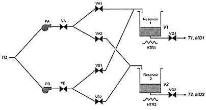
DURESS (DUal REservoir System Simulation) II is a thermal-hydraulic process control microworld that was designed to be representative (Brunswik, 1956) of industrial process control systems, thereby promoting generalizability of research results to operational settings (Vicente, 1991). The physical structure of DURESS II, illustrated in Fig. 6.1, consists of two redundant feedwater streams (FWSs) that can be configured to supply water to either, both, or neither of two reservoirs. Each reservoir has associated with it an externally determined demand for water that can change over time. The work domain purposes are twofold: to keep each of the reservoir temperatures (T1 and T2) at a prescribed temperature (40° C and 20° C, respectively), and to satisfy the current mass (water) output demand rates (MO1 and MO2). To accomplish these goals, workers have control over eight valves (VA, VA1, VA2, VO1, VB, VB1, VB2, and VO2), two pumps (PA and PB), and two heaters (HTR1 and HTR2). All of these components are governed by first-order lag dynamics, with a time constant of 15 s for the heaters and 5 s for the remaining components. Other important variables include the system input temperature (TO), and the volumes for both reservoirs (V1 and V2).
TABLE 6.1 The Aspects of Complexity Outlined in Chapter I, as Represented in This Case Study
FIG. 6.1. A schematic diagram of the DURESS II process control microworld, showing the various components and their topological connections.
Figure 6.1 depicts a schematic diagram of DURESS II. Beginning on the extreme left, the normal inlet water temperature is 10° C. The input water stream splits and flows to two pumps (PA and PB) that operate as discrete switches (on or off). The maximum flow rate through each pump is 10 units/s.
The next set of components are the primary valves (VA and VB), which have a continuous range from 0 to 10. From these primary valves, each FWS splits into two secondary valves connecting each stream to both reservoirs. The secondary valves (VA1, VA2, VB1, and VB2) operate in the same manner as the primary valves. The water then flows to each of the two reservoirs, where it is heated and removed, through the use of the heaters (HTR1 and HTR2) and the output valves (VO1 and VO2), in order to meet the temperature and demand goals, respectively. The reservoirs have a maximum capacity of 100 units.
The heaters (HTR1 and HTR2) also have a continuous range of 0 to 10. The goals for the water temperatures in the reservoirs (T1 and T2) have a tolerance of 13 2°C.
Finally, the outlet valves (VO1 and VO2) are used to meet the demand goals. These valves operate in the same manner as the other valves, except that their maximum setting is 20. The goal area is ±1 unit around the desired level, and moves as a function of changes in the demand.
Sources of Complexity
In this subsection, the nature of the demands imposed by DURESS II are revealed by describing it in terms of the sources of complexity identified in chapter 1 (see Table 6.1).1 Some sources of complexity are not adequately represented by DURESS II because it is only a microworld. For those situations, we have also described how the respective dimension would manifest itself on a larger scale in the generic application domain of industrial process control:
1. Large problem spaces—There are 37 variables that can be used to meaningfully describe DURESS II. Only a subset of these are shown in Fig. 6.1. Table 6.2 provides a complete list of the variables, with definitions for each. In subsequent chapters, we refer to these variables during our CWA of DURESS II. In an industrial-scale process control plant, the number of variables is typically several thousand.
2. Social—DURESS II is only a microworld, so it is of small enough scale that it can be operated by a single worker. However, industrial-scale process control plants require cooperation between many individuals, including: plant manager, plant engineers, control room operators, field operators, and maintenance technicians.
3. Heterogeneous perspectives—The individuals just described have different interests and thus hold different perspectives on the very same plant. For example, a plant manager will be interested in production and safety goals, whereas a field operator will be interested in finding the location of a particular piece of equipment. These different perspectives must somehow be resolved to achieve effective communication and coordination.
4. Distributed—The aforementioned individuals are also physically distributed. For example, field operators spend much of their time out in the plant itself, whereas plant managers and engineers are frequently located in a separate office area. Despite their different locations, these individuals must work together if a plant is to work effectively.
5. Dynamic—As shown in Table 6.3, which provides a partial list of the equations governing the behavior of the process, DURESS II is governed by first-order dynamics. As a result, there is a lag between worker actions and their full effects on the work domain. Because the effects of their actions are delayed, workers have to anticipate the future state of the work domain and act well before the point when a response is desired.
6. Potentially high hazards—There are a number of actions that can lead to equipment failures in DURESS II: (a) If either pump is turned on without any of the downstream valves being opened, the pump will fail after approximately 5 s; (b) it is possible to overflow either of the reservoirs, if the input flow rate is consistently greater than the output flow rate; (c) heating an empty reservoir for an extended period will damage the reservoir; (d) causing the water in the reservoir to boil also damages the work domain. Although these failures do not threaten the environment or human life, as can faults in industrial systems, they nevertheless represent situations to be avoided by workers.
TABLE 6.2 Complete List of Process Variables in DURESS II
7. Many coupled subsystems—The equations in Table 6.3 show that there are strong interactions governing the behavior of DURESS II. For example, the process consists of two FWSs, each of which can be coupled to either reservoir. This many-to-many mapping can create interactions between subsystems. In addition, the mass and energy topologies for DURESS II are also coupled. Specifically, the state of the temperature goal is affected, not only by the heater setting, but also by the inflow of cold water into the reservoir that is used to satisfy the demand goal. This intergoal constraint creates an interaction that must be respected by workers.
8. Automated—Process control systems such as DURESS II are almost always automated, being controlled by negative feedback control systems. Aside from relieving workers from the tedious job of having to manually control the process on a regular basis, automation can also frequently result in economic gains due to more efficient control. However, automation is fallible, thereby requiring worker involvement. Not only can automation fail, but it is not capable of controlling the process during all fault situations (see later discussion). Consequently, it is important that workers supervise the automation to ensure that it is operating as designed, and take over control during faults, if necessary. Note, however, that one of the purposes of CWA is to determine if, and how, the process should be automated. Following the philosophy outlined in chapter 5, automation design is an output from, rather than an input to, CWA.
9. Uncertain data—The data about the state of DURESS II would be obtained from sensors placed at particular locations in the plant. These data would be subject to several types of uncertainty. First, the sensors are not perfectly accurate, and thus the resulting readings always have at least some noise. Second, sensors can fail and thereby provide no information or misleading information, depending on their failure mode. Third, the data available are also limited by sensor technology. There are some variables (e.g., energy) that we might like to measure but that cannot be sensed with existing technology. It may be possible to derive these variables analytically from other sensed data using models or rules. However, the resulting data are still limited by the reliability of the original sensor readings and the fidelity of the models or rules used for the derivation. Fourth, the data are also limited by the number and placement of sensors. If sensors are not available in certain places, then the true state of the work domain in that location may be uncertain.
TABLE 6.3 Some of the Equations Governing the Behavior of Half of DURESS II
10. Mediated interaction via computers—As with most other process control systems, many of the variables that describe the state of DURESS II (e.g., energy in the reservoir, heat transfer from the heater) cannot be directly and reliably observed by unaided human perceptual systems. In the past, these variables were displayed to workers...