- 680 pages
- English
- ePUB (mobile friendly)
- Available on iOS & Android
eBook - ePub
Hydraulics of Spillways and Energy Dissipators
About this book
An unsurpassed treatise on the state-of-the-science in the research and design of spillways and energy dissipators, Hydraulics of Spillways and Energy Dissipators compiles a vast amount of information and advancements from recent conferences and congresses devoted to the subject. It highlights developments in theory and practice and emphasizing top
Trusted by 375,005 students
Access to over 1.5 million titles for a fair monthly price.
Study more efficiently using our study tools.
Information
Section I: Spillways
1
Spillways: Functions and Classification
1.1 INTRODUCTION
“He who creates a potential danger is responsible for doing everything within human power to control it.”
The function of a spillway can be best illustrated as emanating from the above well-known legal argument. Impounding large quantity of water behind a dam creates the danger of a dam-break flood wave, which could have catastrophic consequences. The safe design of a dam to avoid such a danger includes a spillway, aptly described as the safety valve of the dam-reservoir system.
1.2 NECESSITY OF A SPILLWAY
Aspillway is designed to prevent overtopping of a dam at a place that is not designed for overtopping. Vischer et al. (1988) discuss the necessity of a spillway with reference to the following questions:
- Is overflowing of the reservoir possible?
- Could overtopping cause a dam failure?
- Could overtopping cause any other damage?
Areservoir will overflow if its capacity is less than the difference between the volumes of inflow and outflow. If a dam can, economically, be made high enough to provide a retention space above Full Supply Level (FSL) to absorb the entire volume of inflow design flood, no spillway would be required and an outlet such as a turbine or sluice would only be needed for regulating/utilizing storage. There are indeed a few dams where spillways were dispensable or a nominal spillway facility was all that was needed; Moric (1997) has reported two such cases. However, in a majority of cases, it is impractical to provide retention capacity above FSL large enough to absorb the inflow design flood and, hence, a special device to surplus the extra quantity of water is required, namely a spillway.
Whether a dam would fail due to overtopping depends largely on the type of the dam in question. The most sensitive structures are earth-fill dams, which—if not specially protected—are destroyed by even a small overtopping. Masonry and concrete dams, as well as gravity and arch dams can withstand overtopping up to certain extent before they fail due to excessive stresses. However, the indirect threat to their stability due to erosion from an immediate downstream, mainly by overflowing impinging jet, would be of more concern. Overtopping of a dam may also cause other damages to the nearby structures that are not designed for such overtopping.
Considering the above, one can conclude that all dams should be constructed with a safety device, in the form of a spillway, against overtopping. The question then arises as to what portion of the total cost of the dam a spillway constitutes. The available information indicates a large variation, ranging from 4% (unlined rock spillways) to 22% (spillways for earth and rock-fill dams). Generally, spillways account for a small portion of the cost in concrete and arch dams as compared to those with earth or rock-fill dams. However, it seems more appropriate to consider the cost of a spillway in terms of each cumec released rather than the cost of the complete spillway structure in relation to the total cost of the dam. Apertinent observation in this regard is provided by Mriouah (1988), of the spillway of Oued el Makhazine dam (Morocco), where increasing the design flood 2.5 times from 3500 to 8600 cumec (dam height increased by 0.5 m) raised the overall cost of the structure by only 3%. This issue can also be considered in terms of dam safety. AUnited States Bureau of Reclamation (USBR) report (1983) states that spillway inadequacy represents about 40% of the dam failure hazards. Compared with this figure, the percentage cost of the spillway, especially from the standpoint of marginal cost, is usually much lower.
1.3 FUNCTIONS OF A SPILLWAY
While the principal function of a spillway is to pass down the surplus water from the reservoir into the downstream river, there are precisely seven functions that can be assigned to spillway as discussed by Takasu et al. (1988).
- Maintaining normal river water functions (compensation water supply)
- Discharging water for utilization
- Maintaining initial water level in the flood-control operation
- Controlling floods
- Controlling additional floods
- Releasing surplus water (securing dam and reservoir safety)
- Lowering water levels (depleting water levels in an emergency)
It may be mentioned that the above functions have been defined for spillways and regulating outlets as per the Cabinet Orders Concerning Structural Criteria for River Administration Facilities and have been applied to all dams constructed in Japan. Part of the function under (1), (2), and (3) are combined with outlets for low water. Facilities providing function (5) are added to (4) or (6) and are collectively called outlets for high water. Function (7) is essentially for reservoir depletion, which is generally accomplished by low-level outlets. Figure 1 shows graphically the above functions in water level-discharge domain.
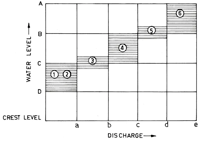
Figure 1 Functions of Spillways and Regulating Outlets. (Takasu et al. 1988) A: Design flood level, B: Surcharge level, C: Initial water level in flood-control operation, D: Minimum operating level, a: Maximum outflow for water supply, b: Initial inflow discharge in the flood-control operation, c: Maximum outflow discharge in the flood-control operation, d: Standard project flood discharge, e: Spillway design flood discharge, 1: Maintenance of normal river water functions (compensation water), 2: Discharge for water utilization, 3: Maintaining initial water level in flood-control operation, 4: Flood control, 5: Additional flood control, 6: Release of surplus water.
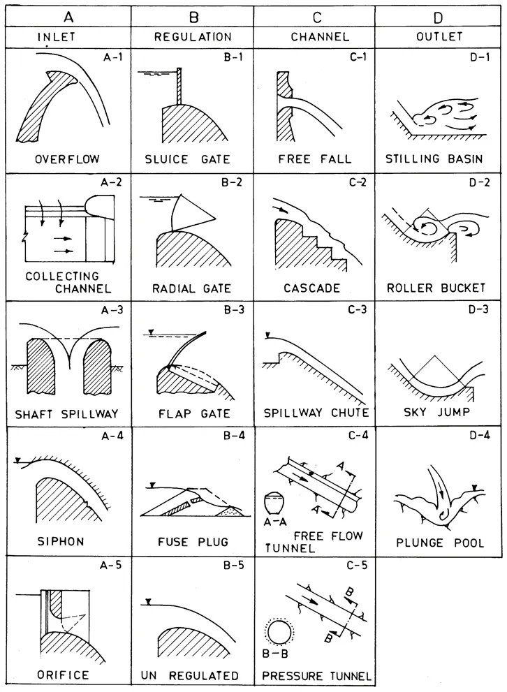
Figure 2 Classification of Spillway (shown in Vischer et al, San Francisco, 1988).
1.4 CLASSIFICATION OF SPILLWAYS
Spillways have been classified according to various criteria
- According to the most prominent feature
- Ogee spillway
- Chute spillway
- Side channel spillway
- Shaft spillway
- Siphon spillway
- Straight drop or overfall spillway
- Tunnel spillway/Culvert spillway
- Labyrinth spillway I. Stepped spillway
- According to Function
- Service spillway
- Auxiliary spillway
- Fuse plug or emergency spillway
- According to Control Structure
- Gated spillway
- Ungated spillway
- Orifice of sluice spillway
Vischer et al. (1988) have proposed a more comprehensive classification that seeks to include essentially all components of the spillway: inlet, regulation or control, discharge carrier, and outlet (including energy dissapators). Their classification—with minor modifications—lists the following alternatives in each component and is shown schematically in Figure 2.
It would seem that if every element could be combined with all the others, (i.e., 5 × 5 × 5 × 3), 375 combinations would be possible, or 375 different types of spillways. However, several combinations are not meaningful, such as radial gate, siphon; free fall, ski jump; etc. Only about 65 combinations seem meaningful, and very few are of practical interest.
REFERENCES
- 1. Moric, P. “Questioning the need for spillways”, International Water Power & Dam Construction, January, 1997.
- 2. Mriouah, D. “Crues Importantes imprevues: cas du barrage de Oued el Makhazine all Maroc”, Q-63, R-82 Proc. 16th ICOLD. San Francisco, June 1988.
- 3. Takasu, S.; Yamaguchi, J. “Principle for selecting type of spillway for flood control dams in Japan”, Q-63, R-19, ibid, 1988.
- 4. “Seminar on Safety Evaluation of Existing Dam for Foreign Engineers - History of Dam Safety Development in the U.S.” USBR, 1983.
- 5. Vischer, D.; Rutschmann, P. “Spillway facilities - Typology and General Safety Questions”, Q-63, R-23, Proc. 16th ICOLD:. San Francisco, June, 1988.
2
Spillway Design: An Overview
2.1 INTRODUCTION
The object of spillway design, which involves two steps, is to provide a safe and adequate spillway structure for the lowest combined cost of the spillway and the dam. The first step in the design involves determining the type and overall size of the spillway structure to suit the anticipated requirements and conditions of the site. A detailed hydraulic and structural design of the spillway structure is the next step. This chapter is concerned with the general procedure of an overall design. An evaluation of the basic data should be the first step in the preparation of the design. This includes the topography and geology as well as flood hydrography, storage, and release requirements. The type, size, and elevation of the crest and whether it will be controlled can also be tentatively decided. Several alternative arrangements might be possible and a final layout could be created on the basis of economic analysis. However, considering analyses of existing spillways could be useful in understanding trends towards the types of spillways for a given set of conditions.
2.2 ANALYSIS OF EXISTING STRUCTURES
It would be of interest to analyze existing structures to see if there was a trend for adopting a particular type of spillway in a given set of condition. Semenkov (1979) analyzed more than 400 projects in terms of parameters L/Hand N for the three main types of spillways: gravity spillways, chute spillways, and tunnel spillways for concrete and earth-fill dams. Here, L and H are the length and height of the dam crest respectively, and N is the power of the flow from the spillway given by 0.0098 × Q × Hb, MW, where Q (cumec) is the discharge and Hb (m)—the difference between the upstream water level and natural river be...
Table of contents
- Cover
- Half Title
- Series Page
- Title Page
- Copyright Page
- Contents
- Dedication
- Preface
- Acknowledgements
- Section I: Spillways
- 1 Spillways: Functions and Classification
- 2 Spillway Design: An Overview
- 3 Spillway Design Flood: Estimation and Selection
- 3.6 Selection of Spillway Design Flood
- 4 Ogee or Overflow Spillways
- 5 Chute and Side Channel Spillways
- 6 Stepped Spillways
- 7 Siphon Spillways
- 8 Shaft Spillways
- 9 Labyrinth and Duckbill Spillways
- 10 Tunnel and Culvert Spillways
- 11 Free Jet and Straight Drop Spillways
- 12 Fuse Plugs and Fuse Gate Spillways
- 13 Spillways for Flood and Sediment Disposal
- 14 Unlined Spillways
- 15 Inflatable Rubber Weirs
- 16 Overtopping Protection of Dams Used as Spillways
- 17 Spillway Crest Gates
- 18 Spillway Construction Stages
- Section II: Energy Dissipators
- 19 Energy Dissipators for Spillways
- 20. Hydraulic Jump Stilling Basins
- 21. Trajectory Buckets
- 22. Solid and Slotted Roller Buckets
- 23. Energy Dissipators for Shaft and Tunnel Spillways
- 24. Impact-Type Energy Dissipators
- 25. Unconventional Designs
- Section III: Cavitation and Air Entrainment
- 26. Cavitation in Spillways and Energy Dissipators
- 27. Air Entrainment and Forced Aeration
- Section IV: Hydraulic Modeling
- 28 Hydraulic Modeling of Spillways and Energy Dissipators
- Index
Frequently asked questions
Yes, you can cancel anytime from the Subscription tab in your account settings on the Perlego website. Your subscription will stay active until the end of your current billing period. Learn how to cancel your subscription
No, books cannot be downloaded as external files, such as PDFs, for use outside of Perlego. However, you can download books within the Perlego app for offline reading on mobile or tablet. Learn how to download books offline
Perlego offers two plans: Essential and Complete
- Essential is ideal for learners and professionals who enjoy exploring a wide range of subjects. Access the Essential Library with 800,000+ trusted titles and best-sellers across business, personal growth, and the humanities. Includes unlimited reading time and Standard Read Aloud voice.
- Complete: Perfect for advanced learners and researchers needing full, unrestricted access. Unlock 1.5M+ books across hundreds of subjects, including academic and specialized titles. The Complete Plan also includes advanced features like Premium Read Aloud and Research Assistant.
We are an online textbook subscription service, where you can get access to an entire online library for less than the price of a single book per month. With over 1.5 million books across 990+ topics, we’ve got you covered! Learn about our mission
Look out for the read-aloud symbol on your next book to see if you can listen to it. The read-aloud tool reads text aloud for you, highlighting the text as it is being read. You can pause it, speed it up and slow it down. Learn more about Read Aloud
Yes! You can use the Perlego app on both iOS and Android devices to read anytime, anywhere — even offline. Perfect for commutes or when you’re on the go.
Please note we cannot support devices running on iOS 13 and Android 7 or earlier. Learn more about using the app
Please note we cannot support devices running on iOS 13 and Android 7 or earlier. Learn more about using the app
Yes, you can access Hydraulics of Spillways and Energy Dissipators by Rajnikant M. Khatsuria in PDF and/or ePUB format, as well as other popular books in Technology & Engineering & Civil Engineering. We have over 1.5 million books available in our catalogue for you to explore.