
- 432 pages
- English
- ePUB (mobile friendly)
- Available on iOS & Android
eBook - ePub
About this book
This outstanding reference provides the complete range of practical and theoretical information - with over 250 detailed illustartions, fugures and table- needed to design, manufacture and operate reliable, efficient gear drive systems, emphasizing parallel shaft and planetary units with spur and helical gearing.
Trusted by 375,005 students
Access to over 1.5 million titles for a fair monthly price.
Study more efficiently using our study tools.
Information
1
TYPES OF GEAR DRIVES: ARRANGEMENTS, TOOTH FORMS
The function of a gearbox is to transmit rotational motion from a driving prime mover to a driven machine. The driving and driven equipment may operate at different speeds, requiring a speed-increasing or speed-decreasing unit. The gearbox therefore allows both machines to operate at their most efficient speeds. Gearboxes are also used to change the sense of rotation or bridge an angle between driving and driven machinery.
The gearbox configuration chosen for a given application is most strongly influenced by three parameters:
Physical arrangement of the machinery
Ratio required between input and output speeds
Torque loading (combination of horsepower and speed)
Other factors that must be considered when specifying a gear drive are:
Efficiency
Space and weight limitations
Physical environment
PHYSICAL ARRANGEMENT
The location of the driving and driven equipment in the mechanical system defines the input and output shaft geometrical relationship. Shaft arrangements can be parallel offset, concentric, right angle, or skewed as shown in Figure 1.1. The material presented in this book focuses on parallel offset and concentric designs.
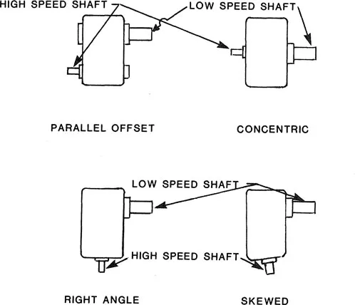
Figure 1.1 Gearbox shaft arrangements.
In the majority of parallel offset units in use, the input and output shafts are horizontally offset; however, vertical offsets are used and any orientation of input to output shaft is possible. Figure 1.2 illustrates a typical horizontally offset parallel shaft gearbox and Figure 1.3 presents a cutaway view of such a unit. In this case there is one input shaft and one output shaft located on opposite sides of the unit. There are many different options available as far as the input and output shaft extensions are concerned. Figure 1.4 shows the various possibilities and presents a system for defining the extensions desired on a gearbox. There may be two inputs driving a single output, such as dual turbines powering a large generator, or two outputs with a single input, such as an electric motor driving a two-stage compressor. Often shaft extensions are used to drive accessories such as pumps or starters.
The minimum amount of offset required is determined by gear tooth stress considerations. The offset of a gearbox incorporating a single mesh, as shown in Figure 1.3, is the sum of the pitch radii of the pinion and gear, otherwise known as the center distance. The pitch radii must be sufficiently large to transmit the system load. An offset greater than the minimum may be required to provide enough space for the machinery incorporated in the system. Figure 1.5 illustrates an accessory drive where the input and output shafts are offset through two meshes to separate the machinery located at these shafts.
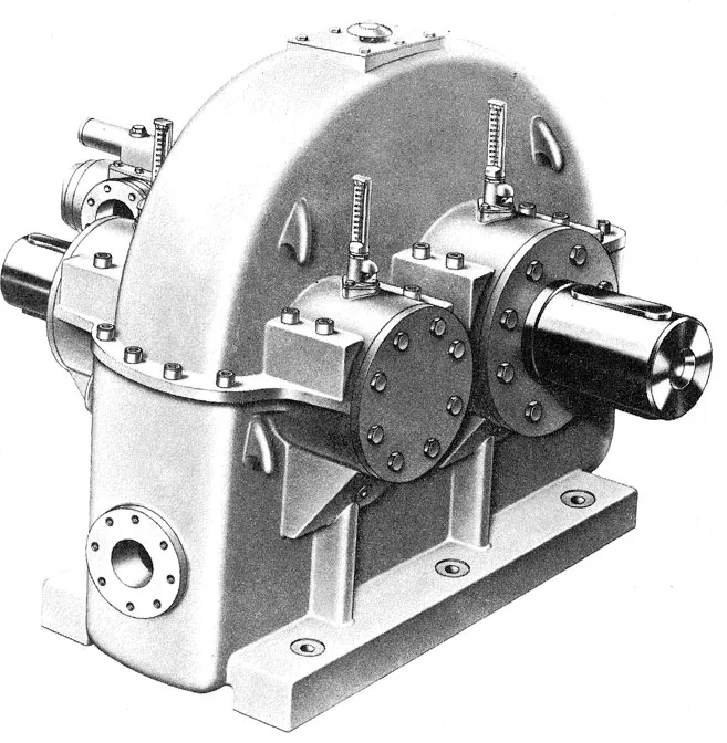
Figure 1.2 Parallel offset gearbox. (Courtesy of American Lohmann Corporation, Hillside, N.J.)
Figure 1.6 illustrates a gearbox with concentric input and output shafts. The driving and driven machinery will therefore be in line. Planetary gearing (described in the next section) has concentric shafts and is used to achieve high ratios in minimum space. It is also possible to package parallel shaft gearing such that the input and output shafts are in line when such a configuration is desired. Figure 1.7 presents external and internal views of a right-angle gear drive.
The gearboxes in Figures 1.3, 1.6, and 1.7 are foot mounted; that is, they are meant to be bolted to a horizontal base through a flange at the bottom of the gear casing. Although this is the most common design, gearboxes can be mounted in many other configurations and operate in attitudes other than horizontal. Figure 1.8 illustrates a flange-mounted unit. Such a gearbox can be operated horizontally or be vertically mounted on a horizontal base. Vertically operating gearbox designs must have special lubrication provisions to provide lubricant to the upper components in the unit and seal the lower end from oil leakage. Figure 1.9 shows yet another mounting configuration. This unit is shaft mounted with a support arm that is fixed to ground to react the gearbox housing torque.
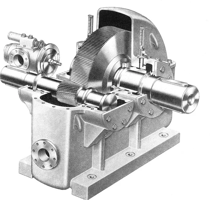
Figure 1.3 Parallel offset gearbox sectional view. (Courtesy of American Lohmann Corporation, Hillside, N.J.)
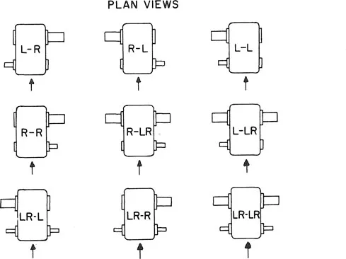
Figure 1.4 Definition of shaft extensions. Parallel shaft-helical and herringbone gear reducers; single, double, and triple reduction. Code; L = left; R = right; arrows indicate line of sight to determine direction of shaft extensions; letters preceding the hyphen refer to number and direction of highspeed shaft extensions; letters following the hyphen refer to number and direction of low speed shaft extensions. (From Ref. 1.)
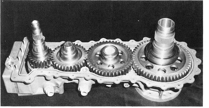
Figure 1.5 Parallel offset accessory drive gearbox. (Courtesy of American Lohmann Corporation, Hillside, N.J.)
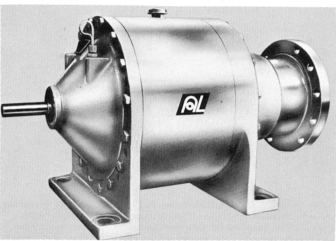
Figure 1.6 Gearbox with concentric input and output shafts. (Courtesy of American Lohmann Corporation, Hillside, N.J.)
GEAR RATIO
There is no limit to the reduction or speed increasing ratio that can be achieved using gearing; however, for high ratios the arrangement of the components can be quite complex. In a simple gear mesh a maximum ratio in the order of 8:1 to 10:1 can be achieved. The amount of speed reduction or increase is simply the ratio of the pitch diameter of the larger gear to the smaller gear. The number of teeth in a gear pair is related to the pitch diameters, so the speed ratio can also be calculated by dividing the larger number of teeth by the smaller. The smaller gear is often called the pinion. To attain a ratio of 10:1, therefore, the gear must be 10 times larger than the pinion and there usually are stress or geometrical limitations on the pinion when this ratio is exceeded. To achieve higher ratios with parallel shaft gearing, stages of meshes are combined as shown in Figure 1.10. This unit has three stages of reduction and achieves ratios on the order of 100:1.
An efficient method of achieving high reduction ratios in minimum space is the use of planetary gearing. This design, completely described in Chapter 9, is illustrated in Figure 1.11. The high-speed sun gear meshes with a number of planets, usually three, which in turn mesh with a ring gear. The ring gear has internal teeth. Either the ring gear or the planet carrier rotate at the low speed of the gear set. Occasionally, all three members are connected to rotating equipment. When the low-speed shaft is either the ring gear or the planet carrier, the ratios in a planetary gearset are:
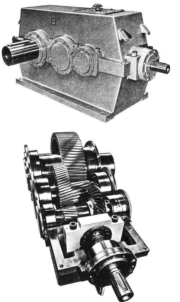
Figure 1.7 Right-angle gear drive. (Courtesy of American Lohmann Corporation, Hillside, N.J.)
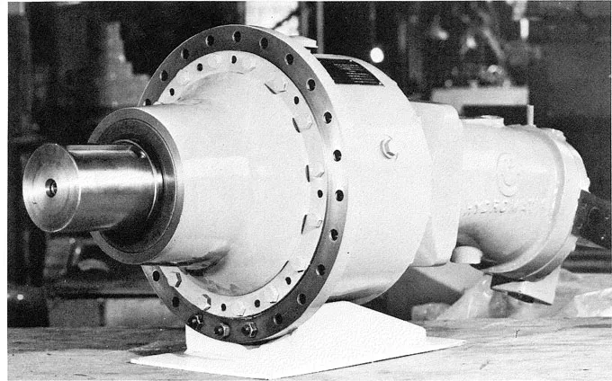
Figure 1.8 Flange-mounted gear unit. (Courtesy of American Lohmann Corporation, Hillside, N.J.)
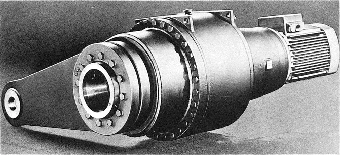
Figure 1.9 Shaft-mounted gearbox. (Courtesy of American Lohmann Corporation, Hillside, N.J.)

Figure 1.10 Multi-stage parallel shaft gearbox. (Courtesy of American Lohmann Corporation, Hillside, N.J.)
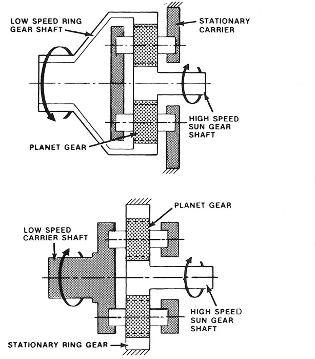
Figure 1.11 Basic planetary gear configurations.
Because of the multiple load path of planetary gearing the horsepower transmitted is divided between several planet meshes and the gear size can be reduced significantly compared to parallel shaft designs. Planetary stages can be linked together to achieve high ratios, as shown in Figure 1.12. This is a three-stage planetary gear with a ratio of 630:1. The first-stage planet carrier drives the second-stage sun gear and the second-stage carrier drives the third-stage sun gear.
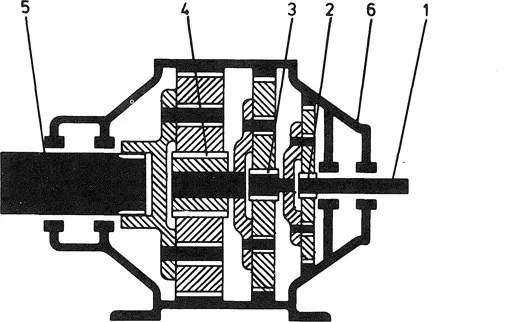
Figure 1.12 Multistage planetary gearbox. High-speed shaft, 1; first planetary stage, 2; second stage, 3; third stage, 4; low-spe...
Table of contents
- Cover
- Half Title
- Title Page
- Copyright Page
- Table of Contents
- Preface
- 1. Types of Gear Drives: Arrangements, Tooth Forms
- 2. Gear Tooth Design
- 3. Gearbox Rating
- 4. Bearings and Seals
- 5. Lubrication Systems
- 6. Materials and Heat Treatments
- 7. Manufacturing Methods
- 8. Gearbox Economics
- 9. Planetary Gear Trains
- 10. Gearbox Installation: Mounting, Alignment, Couplings
- 11. Gear Unit Operation: Testing, Startup, Condition Monitoring
- 12. Maintenance and Failure Analysis: Scheduled Maintenance Actions
- Appendix
- Index
Frequently asked questions
Yes, you can cancel anytime from the Subscription tab in your account settings on the Perlego website. Your subscription will stay active until the end of your current billing period. Learn how to cancel your subscription
No, books cannot be downloaded as external files, such as PDFs, for use outside of Perlego. However, you can download books within the Perlego app for offline reading on mobile or tablet. Learn how to download books offline
Perlego offers two plans: Essential and Complete
- Essential is ideal for learners and professionals who enjoy exploring a wide range of subjects. Access the Essential Library with 800,000+ trusted titles and best-sellers across business, personal growth, and the humanities. Includes unlimited reading time and Standard Read Aloud voice.
- Complete: Perfect for advanced learners and researchers needing full, unrestricted access. Unlock 1.5M+ books across hundreds of subjects, including academic and specialized titles. The Complete Plan also includes advanced features like Premium Read Aloud and Research Assistant.
We are an online textbook subscription service, where you can get access to an entire online library for less than the price of a single book per month. With over 1.5 million books across 990+ topics, we’ve got you covered! Learn about our mission
Look out for the read-aloud symbol on your next book to see if you can listen to it. The read-aloud tool reads text aloud for you, highlighting the text as it is being read. You can pause it, speed it up and slow it down. Learn more about Read Aloud
Yes! You can use the Perlego app on both iOS and Android devices to read anytime, anywhere — even offline. Perfect for commutes or when you’re on the go.
Please note we cannot support devices running on iOS 13 and Android 7 or earlier. Learn more about using the app
Please note we cannot support devices running on iOS 13 and Android 7 or earlier. Learn more about using the app
Yes, you can access Gear Drive Systems by Peter Lynwander in PDF and/or ePUB format, as well as other popular books in Technology & Engineering & Industrial Design. We have over 1.5 million books available in our catalogue for you to explore.