- 236 pages
- English
- ePUB (mobile friendly)
- Available on iOS & Android
eBook - ePub
Refrigeration Equipment
About this book
Refrigeration Equipment is a clear, practical guide to the installation, testing and servicing of industrial and domestic refrigeration equipment.
Refrigeration technicians, who are poorly provided with good reference material, will welcome the author's hands-on approach. Other readers will include trainees on in-plant industry courses, building service engineers and maintenance staff in the frozen food industry, supermarkets, hotels and hospitals. It also provides a text from NVQs (C&G 6007) and other vocational courses).
This revised edition has been updated throughout, and includes a new section on the topical subject of alternative refrigerants and, for the first time, a chapter on the principles of air conditioning.
Trusted by 375,005 students
Access to over 1.5 million titles for a fair monthly price.
Study more efficiently using our study tools.
Information
1
Introduction
To be able to install, commission and carry out maintenance or repairs to even the most basic refrigeration system, it is essential that the engineer has a sound knowledge of the system operation, the functions of the various valves, the controls employed in the system, and the specialist tools or equipment necessary to carry out those tasks.
Generally, larger refrigeration companies employ engineers who specialize in servicing and others involved only with the installation of equipment. Smaller companies require engineers to be proficient in both service and installation practice.
This manual deals with the fundamental principles of service, installation and commissioning, but not necessarily to any specific manufacturer’s recommendation or equipment.
The service engineer
Obviously the need for service and maintenance on existing plant exceeds the demand for new installations and for this reason it is essential that all engineers are conversant with the various service operations and diagnostic procedures; they are dealt with in Part One.
The engineer must be conversant with the type and location of system service valves, with the gauge manifold and all types of gauges used with refrigeration equipment.
The ability to diagnose why a system is not operating correctly, or merely to establish that it is providing optimum service, starts with the fitting of gauges to record either the operating or static pressure of the plant, depending upon the circumstances.
A high percentage of service calls are due to refrigerant leakage either from fractured pipework joints or from defective components which have been subjected to internal or external corrosion to cause a leak.
Often a service call can result in the replacement or relocation of a component, necessitating a change in the pipework design or route – so the two aspects, servicing and installation, cannot be completely divorced from each other.
The response to a service call is a venture into the unknown and the engineer must be prepared for every eventuality.
Installation procedures
Part Two starts with the most commonly encountered pipework fittings, methods of joining and supporting pipework and the important subject of oil traps to ensure oil return to the compressor for adequate lubrication at all times.
Installations vary according to system design, system application and the location of major components, of which the most important aspects are discussed. The requirement for ancillary controls and components also depends upon the system design.
The installation of compressors and drive couplings, including the correct alignment of drive options and drive belt tensioning, is of utmost importance, whether in a new installation, in replacement or during commissioning. The necessity to provide electrical protection for both equipment and personnel must not be overlooked.
System evacuation for newly installed systems and after remedial service has taken place must be given priority if reliability is to be achieved. Decontamination of systems often presents problems unless the prescribed and proved procedures are adopted.
For all of these requirements the correct, logical and safe practices are explained. Unless good refrigeration practices are observed, not only does a system’s reliability become suspect; there is also the danger of polluting the atmosphere in general, including the immediate vicinity where other people may be affected to the detriment of their health and working conditions.
Vapour compression systems
The basic refrigeration system comprises four major components (Figure 1):
1 The evaporator or cooling coil, which creates a cool surface to which heat may transfer from the refrigerated space or product and be absorbed by the cooling agent (refrigerant) circulated within.
2 The compressor, which circulates the cooling agent and changes its state by compression, creating a pressure differential at B.
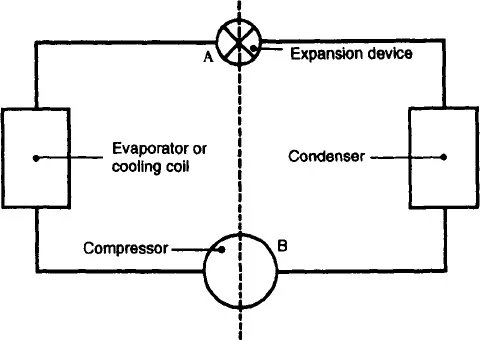
Figure 1 Basic vapour compression system
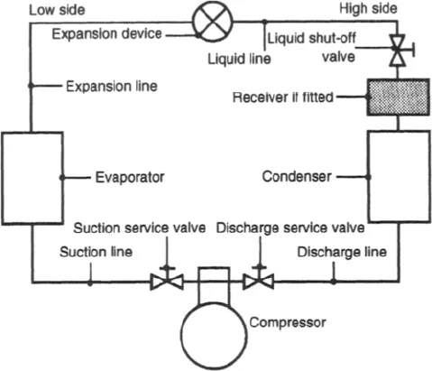
Figure 2 Vapour compression system
3 The condenser, which provides a sufficient surface area to be able to reject the heat absorbed by the cooling agent or refrigerant, conveyed from the evaporator.
4 The expansion device or refrigerant metering control, which regulates the flow of refrigerant to the evaporator and creates a pressure differential at A.
Some systems include a liquid receiver, which acts as a storage container for surplus refrigerant during normal operation and is able to retain the bulk of the system operating charge whilst certain service operations are performed.
Refrigerant is conveyed to and from these components by interconnecting pipework, as in Figure 2.
It will be seen from Figures 1 and 2 that the system is divided. The low side runs from the outlet of the expansion device to the inlet of the compressor, and the high side from the outlet or discharge of the compressor to the inlet of the expansion device. The compressor and expansion device are the two components which create a pressure differential within the system, and malfunction of either will affect the system operation.
Obviously, the presence of high and low pressures within the system necessitates the use of valves to isolate those pressures during service operations (Figure 2). These valves are known as service valves and, although the design and position of the valves may vary, their function remains the same.
Part One
Servicing
Since this handbook was first published changes have taken place which affect some of the previous recognized practices.
New and replacement refrigerants and lubricating oils have been introduced and no doubt many more are contemplated. A selection of these are dealt with in this edition.
It will also be noted that some refrigerants which have been phased out and some which will be phased out by the year 2000 are still mentioned. They have been included in this edition for reference and comparison.
Some calculations based on the use of these substances remain to describe the principle. Systems charged with these refrigerants are still operating nationwide and need to be considered.
2
Service valves and gauges
System service valves
When servicing or commissioning any equipment it is necessary to record the system pressures by fitting pressure gauges. To make this possible, all commercial systems generally include at least three service valves: suction, discharge and liquid shut-off.
Suction and discharge service valves may be located on the compressor body of both reciprocating open-type compressors and semi-hermetic motor compressors, but on some compressor designs the service valves may be an integral part of the compressor head assembly. Hermetic motor compressors and some semi-hermetic models do not feature a discharge service valve, but the high side pressure may be obtained from the service valve on the liquid receiver or via a Schraeder-type valve fitted into the discharge line or on the receiver itself.
Service valves can be set to three different positions (Figure 3):
Front seated position The valve stem is turned fully clockwise to effectively stop the flow of refrigerant vapour from the suction line union on the low pressure side of the compressor and to the discharge line union on the high pressure side of the compressor.
Back seated position The valve stem is turned fully counter-clockwise to stop the flow of refrigerant vapour to the gauge port of the service valve.
Midway position The valve stem is turned either clockwise or counter-clockwise to leave the valve unseated. Thus refrigerant vapour can flow from the suction line and also to the discharge line and at the same time pass through the gauge port, to the gauge hose and to the relevant pressure gauge.
The liquid shut-off valve may be located at the outlet of the receiver. It is a single seating valve, i.e. it is either open or closed (Figure 4). On systems which do not have a receiver the valve design will be similar to that of a suction or discharge service valve and will have a gauge connection. When closed or fully front seated, this valve will stop the flow of liquid refrigerant from the condenser or receiver to the expansion device.
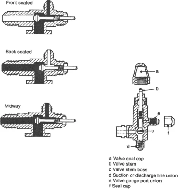
Figure 3 Service valve
Performing service operations, carrying out repairs, commissioning a system and diagnosing faults involve the use of these valves in addition to test equipment, which will be dealt with separately. are three external hose connections, and at eith...
Table of contents
- Front Cover
- Refrigeration Equipment
- Title Page
- Copyright
- Contents
- Preface
- Acknowledgements
- 1 Introduction
- Part One Servicing
- Part Two Installation and Commissioning
- Part Three Replacement Refrigerants and Ozone Depletion
- Appendix A Fundamental principles of air conditioning
- Appendix B Refrigerant data
- Index
Frequently asked questions
Yes, you can cancel anytime from the Subscription tab in your account settings on the Perlego website. Your subscription will stay active until the end of your current billing period. Learn how to cancel your subscription
No, books cannot be downloaded as external files, such as PDFs, for use outside of Perlego. However, you can download books within the Perlego app for offline reading on mobile or tablet. Learn how to download books offline
Perlego offers two plans: Essential and Complete
- Essential is ideal for learners and professionals who enjoy exploring a wide range of subjects. Access the Essential Library with 800,000+ trusted titles and best-sellers across business, personal growth, and the humanities. Includes unlimited reading time and Standard Read Aloud voice.
- Complete: Perfect for advanced learners and researchers needing full, unrestricted access. Unlock 1.5M+ books across hundreds of subjects, including academic and specialized titles. The Complete Plan also includes advanced features like Premium Read Aloud and Research Assistant.
We are an online textbook subscription service, where you can get access to an entire online library for less than the price of a single book per month. With over 1.5 million books across 990+ topics, we’ve got you covered! Learn about our mission
Look out for the read-aloud symbol on your next book to see if you can listen to it. The read-aloud tool reads text aloud for you, highlighting the text as it is being read. You can pause it, speed it up and slow it down. Learn more about Read Aloud
Yes! You can use the Perlego app on both iOS and Android devices to read anytime, anywhere — even offline. Perfect for commutes or when you’re on the go.
Please note we cannot support devices running on iOS 13 and Android 7 or earlier. Learn more about using the app
Please note we cannot support devices running on iOS 13 and Android 7 or earlier. Learn more about using the app
Yes, you can access Refrigeration Equipment by A C Bryant in PDF and/or ePUB format, as well as other popular books in Technology & Engineering & Civil Engineering. We have over 1.5 million books available in our catalogue for you to explore.