Carpentry and Joinery 2 is the second in a series of three books, which together provide an authoritative and thoroughly practical guide to carpentry and joinery for students following City & Guilds and CITB courses, NVQ candidates, and students working towards an Institute of Carpenters qualification. This book is also ideal for a wide range of amateur and professional woodworkers.
Volume 2 builds on the fundamental knowledge introduced in volume 1, by covering more advanced topics and procedures, including machine tools. Essential 'back-up' topics are presented throughout the text to revise the key aspects covered in volume 1. The reader is shown how to apply this basic theory to actual carpentry and joinery practice in a highly illustrated, easily accessible text.
The third edition has been fully updated in line with changes to the Building Regulations and current legislation, the third edition also incorporates developments in current best practice, with a comprehensive match to the latest qualifications in Wood Occupations.

- 226 pages
- English
- ePUB (mobile friendly)
- Available on iOS & Android
eBook - ePub
Carpentry and Joinery 2
About this book
Trusted by 375,005 students
Access to over 1.5 million titles for a fair monthly price.
Study more efficiently using our study tools.
Information
1 Site setting-out
Setting-out involves different processes; one or more of which will be necessary before starting any constructional work. They include the following:
• linear measurement,
• working to a straight line,
• setting out angles,
• setting out concentric curves,
• establishing a datum,
• levelling,
• vertical setting-out.
The accuracy with which these are carried out will determine the final outcome of the work.
1.1 Linear measurement
Measuring distances greater than 1 m generally means using a retractable tape measure.
1.1.1 Measuring tapes
Available in a variety of lengths, made of steel or fibreglass coated with polyvinyl chloride (PVC) (linen tapes are now obsolete because of their tendency to stretch, they have been superseded by PVC-coated fibreglass types). Tapes under 10 m in length have a built-in lockable automatic retractable rewind mechanism (see Volume 1, Section 5.1.3), longer tapes are rewound manually.
Digital measuring tapes are available like the one shown in Fig. 1.1. Its liquid crystal display (LCD) panel is battery operated with automatic cut-off – measuring accuracies of ±1 mm can be expected up to 5 m.
In use, the accuracy of a measuring tape will depend on:
• the clarity of its graduations;
• whether it is held in the correct plane (Fig. 1.2);
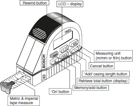
Fig. 1.1 Bosch digital measuring tape
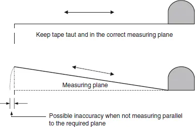
Fig. 1.2 Using a tape measure
• the amount of, or lack of, tension being applied to the tape – very important when measuring long distances;
• readings being correctly taken from left to right.
Measurement errors frequently occur when measurements are transferred from drawing to site. An example of how errors can be reduced is shown in Fig. 1.3.
Figure 1.3(a) represents a plan view of individually dimensioned wall recesses. If, on transfer, one of these distances was wrongly measured it would not only affect the overall length of the wall, but also have a cumulative effect on all those measurements which followed.
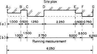
Fig. 1.3 Transferring measurements from a drawing to site
For example, an error between points B and C would result in points D, E, F, and G being wrongly positioned.
Figure 1.3(b) shows how measurements can be transferred by using ‘running measurements’. The tape is run once from A to G (total length), all intermediate measurements are referred back to A as shown in the build-up of the running total.
1.1.2 Laser digital distance metres (Fig. 1.4)
These instruments are intended to measure distances (lengths, heights), a typical example of use is shown in Fig. 1.5. When required the instalment can also calculate areas and volumes.
They operate by projecting an intensive beam of light (laser beam) onto a wall or object. When switched on to the required programme (Fig. 1.4) the length of the beam is automatically measured, the resulting distance, area, or volume is then automatically portrayed onto the LCD panel.
Safety (also see section 1.7.8)
As with any instrument or tool using an exposed laser beam as described in Fig. 1.4, special safety precautions must be taken before and during their use; for example:
• Operating manual (operational safety instructions) must be read completely, understood, and strictly followed before the instrument or tool is used.
• Operatives must be informed of the operating dangers and protective measures.
• Never remove warning signs from the unit.
• Never look into a laser beam, especially not with optical aids such as glasses or binoculars, etc.
• Laser-viewing glasses are not protective glasses against laser beams.
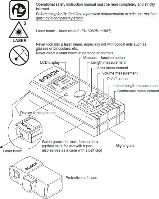
Fig. 1.4 Bosch Laser ‘Rangefinder’
• Never direct a laser beam at persons or animals.
• Before using for the first time a practical demonstration of safe use must be given by a competent person.
1.1.3 Sloping sites
Figure 1.6 shows how horizontal measurements over sloping or obstructed ground are carried out. Pegs or posts are positioned on or driven into the ground to act as intermediate measuring stations, each distance is registered separately to produce a final running total.
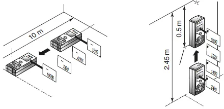
As the ‘Rangefinder’ is moved horizontally or vertically from a solid object or surface – distances are registered on the LCD panel
Note: The instrument is also capable of measuring lengths by taking indirect readings
Fig. 1.5 Measuring distances using a Bosch Laser ‘Rangefinder’
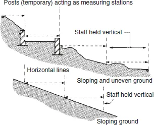
Fig. 1.6 Measuring sloping sites
1.1.4 Transferring measurements
Simple measuring aids like those shown in Fig. 1.7 are very accurate and useful. Probably the simplest method as shown in Fig. 1.7(a) involves the use of a small-sectioned length of timber as a ‘rod’. In this case the actual brick reveal distances are transferred directly to the rod with a pencil or marker. Measurement transfers of this nature are often made from site to workshop where an item of joinery has to fit over or into a specific space or opening.
A ‘pinch rod’ (Fig. 1.7(b)), on the other hand, consists of two short lengths of timber, one of which slides on the other to enable its total length to be varied. This is ideal for measuring between openings – once set, the pieces are held in that position with nails or a cramp, etc.
As shown in Fig. 1.8 a more sophisticated method of taking either vertica...
Table of contents
- Front Cover
- Half Title
- Title Page
- Copyright
- Contents
- Foreword by W. R. Rose
- Foreword by David R. Winson
- Preface
- Acknowledgements
- CHAPTER ONE SITE SETTING-OUT
- CHAPTER TWO FENCES AND HOARDING
- CHAPTER THREE FORMWORK (TEMPORARY WORK)
- CHAPTER FOUR TURNING PIECES AND ARCHED CENTRES UP TO 1-M SPAN
- CHAPTER FIVE GROUND FLOORS
- CHAPTER SIX SINGLE UPPER FLOORS
- CHAPTER SEVEN SINGLE TIMBER FLAT ROOFS
- CHAPTER EIGHT ROOFS OF EQUAL PITCH
- CHAPTER NINE PARTITIONS (NON-LOAD BEARING)
- CHAPTER TEN SCAFFOLDING
- Index
Frequently asked questions
Yes, you can cancel anytime from the Subscription tab in your account settings on the Perlego website. Your subscription will stay active until the end of your current billing period. Learn how to cancel your subscription
No, books cannot be downloaded as external files, such as PDFs, for use outside of Perlego. However, you can download books within the Perlego app for offline reading on mobile or tablet. Learn how to download books offline
Perlego offers two plans: Essential and Complete
- Essential is ideal for learners and professionals who enjoy exploring a wide range of subjects. Access the Essential Library with 800,000+ trusted titles and best-sellers across business, personal growth, and the humanities. Includes unlimited reading time and Standard Read Aloud voice.
- Complete: Perfect for advanced learners and researchers needing full, unrestricted access. Unlock 1.5M+ books across hundreds of subjects, including academic and specialized titles. The Complete Plan also includes advanced features like Premium Read Aloud and Research Assistant.
We are an online textbook subscription service, where you can get access to an entire online library for less than the price of a single book per month. With over 1.5 million books across 990+ topics, we’ve got you covered! Learn about our mission
Look out for the read-aloud symbol on your next book to see if you can listen to it. The read-aloud tool reads text aloud for you, highlighting the text as it is being read. You can pause it, speed it up and slow it down. Learn more about Read Aloud
Yes! You can use the Perlego app on both iOS and Android devices to read anytime, anywhere — even offline. Perfect for commutes or when you’re on the go.
Please note we cannot support devices running on iOS 13 and Android 7 or earlier. Learn more about using the app
Please note we cannot support devices running on iOS 13 and Android 7 or earlier. Learn more about using the app
Yes, you can access Carpentry and Joinery 2 by Brian Porter,Chris Tooke in PDF and/or ePUB format, as well as other popular books in Technology & Engineering & Civil Engineering. We have over 1.5 million books available in our catalogue for you to explore.