Television today means moving pictures in colour with sound, brought to the viewer by terrestrial or satellite broadcast, cable or recording medium. The technique and processes necessary to create, record, deliver and display television pictures form the major part of this book.
Television Fundamentals is written in clear English, with a minimum of mathematics. Readers are taken, in a logical sequence of small steps, through the fundamental principles of the subject, with practical applications and a guide to troubleshooting included. Encoding, decoding, recording and transmission are treated in depth.
John Watkinson is an independent consultant in digital video, audio and data technology. He is a Fellow of the AES and presents lectures, conference papers and training courses worldwide. he is the author of numerous other Focal Press books, including: Compression in Video and Audio, The Art of Digital Audio and The Art of Digital Video (now in their second editions), the Art of Data Recording, An Introduction to Digital Audio, An Introduction to Digital Video, The Digital Video Tape Recorder and RDAT.
- 320 pages
- English
- ePUB (mobile friendly)
- Available on iOS & Android
eBook - ePub
Television Fundamentals
About this book
Trusted by 375,005 students
Access to over 1 million titles for a fair monthly price.
Study more efficiently using our study tools.
Information
Subtopic
Communication StudiesChapter 1
Video concepts
In this chapter the concepts of image delivery are discussed, beginning with the scanning and synchronizing of monochrome cameras and displays. The concepts of contrast and resolution are discussed, along with an introduction to sampling theory and the two-dimensional spectra of analog video signals. Colour television is considered in Chapter 2. The term 'television' literally means to see at a distance and is generally taken to imply a broadcast. Where there is distance but no public broadcast, such as in security systems, the term 'closed circuit television' (CCTV) is used. In contrast, the term 'video' simply means 'I see'. Consequently we use devices such as video monitors and video recorders whether or not there is a transmission, but we would always use the term television transmitter.
1.1 Scanning
Monochrome, or 'black and white', television was developed some time before the addition of colour. The explanation of television principles is also simplified by considering monochrome systems first before complicating matters with colour.
It is difficult to convey two-dimensional images from one place to another directly, whereas electrical and radio signals are easily carried. The problem is to convert a two-dimensional image into a single voltage changing with time. The solution is to use the principle of scanning. Figure 1.1(a) shows that the camera produces a video signal whose voltage is a function of the image brightness at a single point on the sensor. This voltage is converted back to the brightness of the same point on the display. The points on the sensor and display must be scanned synchronously if the picture is to be re-created properly. If this is done rapidly enough it is largely invisible to the eye. Figure 1.1(b) shows that the scanning is controlled by a triangular or sawtooth waveform in each dimension which causes a constant-speed forward scan followed by a rapid return or flyback. As the horizontal scan is much more rapid than the vertical scan the image is broken up into lines which are not quite horizontal.
In the example of Figure 1.1(b), the horizontal scanning frequency or line rate, Fh, is an integer multiple of the vertical scanning frequency or frame rate and a progressive scan system results in which every frame is identical. Figure 1.1(c) shows an interlaced scan system in which there is an integer number of lines in two vertical scans or fields. The first field begins with a full line and ends on a half line and the second field begins with a half line and ends with a full line. The lines from the two fields interlace or mesh on the screen. Current terrestrial broadcast systems such as PAL and NTSC use interlace. The additional complication of interlace has both merits and drawbacks which will be discussed in Section 1.16.
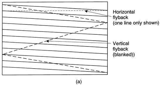
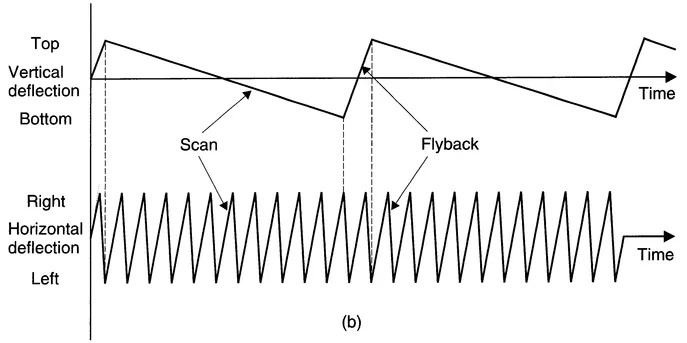
Figure 1.1 Scanning converts two-dimensional images into a signal which can be sent electrically. In (a) the scanning of camera and display must be identical. The scanning is controlled by horizontal and vertical sawtooth waveforms (b).
1.2 Synchronizing
It is vital that the horizontal and vertical scanning at the camera is simultaneously replicated at the display. This is the job of the synchronizing or sync system which must send timing information to the display alongside the video signal. In very early television equipment this was achieved using two quite separate or non-composite signals. Figure 1.2(a) shows one of the first (US) television signal standards in which the video waveform had an amplitude of 1 volt pk-pk and the sync signal had an amplitude of 4 volts pk-pk. In practice, it was more convenient to combine both into a single electrical waveform then called composite video which carries the synchronizing information as well as the scanned brightness signal. The single signal is effectively shared by using some of the flyback period for synchronizing. The 4 volt sync signal was attenuated by a factor of ten and added to the video to produce a 1.4 volt pk-pk signal. This was the origin of the 10:4 video:sync relationship of US television practice. Later the amplitude was reduced to 1 volt pk-pk so that the signal had the same range as the original non-composite video. The 10:4 ratio was retained. As Figure 1.2(b) shows, this ratio results in some rather odd voltages and, to simplify matters, a new unit called the IRE unit (after the Institute of Radio Engineers) was devised. Originally this was defined as one per cent of the video voltage swing, independent of the actual amplitude in use, but it came in practice to mean one per cent of 0.714 volts. In European systems shown in Figure 1.2(c) the messy numbers were avoided by using a 7:3 ratio and the waveforms are always measured in millivolts. Whilst such a signal was originally called composite video, today it would be referred to as monochrome video or Ys, meaning luminance carrying syncs, although in practice the 's' is often omitted.
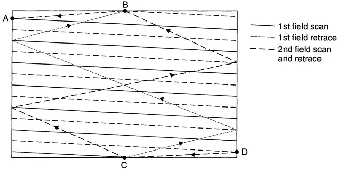
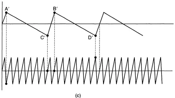
Figure 1.1 (Continued) Where two vertical scans are needed to complete a whole number of lines, the scan is interlaced as shown in (c). The frame is now split into two fields.
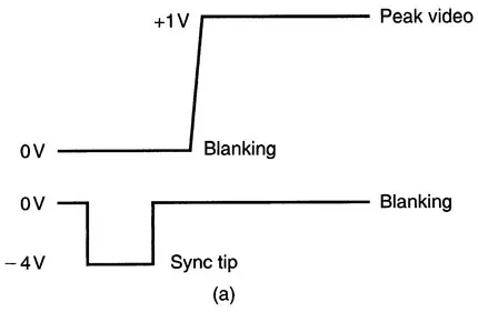
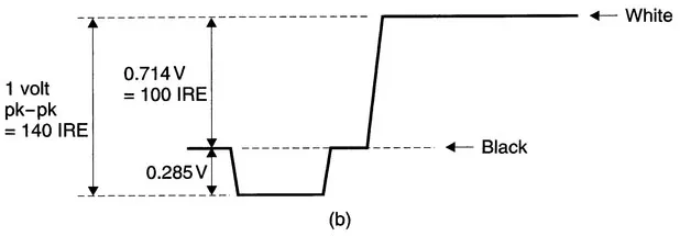
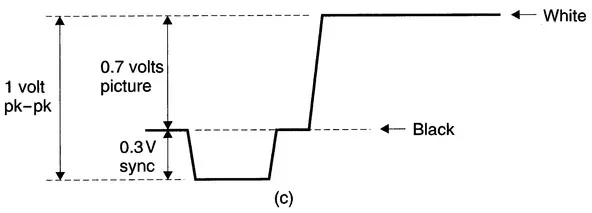
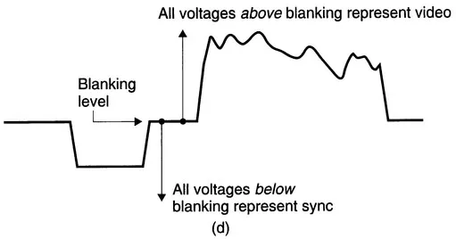
Figure 1.2 Early video used separate vision and sync signals shown in (a). The US one volt video waveform in (b) has 10:4 video/sync ratio, (c) European systems use 7:3 ratio to avoid odd voltages, (d) Sync separation relies on two voltage ranges in the signal.
Figure 1.2(d) shows how the two signals are separated. The voltage swing needed to go from black to peak white is less than the total swing available. In a standard analog video signal the maximum amplitude is 1 volt pk-pk. The upper part of the voltage range represents the variations in brightness of the image from black to white. Signals below that range are 'blacker than black' and cannot be seen on the disolay. These signals are used for synchronizing.
Figure 1.3(a) shows the line synchronizing system part-way through a field or frame. The part of the waveform which corresponds to the forward scan is called the active line and during the active line the voltage represents the brightness of the image. In between the active line periods are horizontal blanking intervals in which the signal voltage will be at or below black. Figure 1.3(b) shows that in some systems the active line voltage is superimposed on a pedestal or black level set-up voltage of 7.5 IRE. The purpose of this set-up is to ensure that the blanking interval signal is below black on simple displays so that it is guaranteed to be invisible on the screen. When set-up is used, black level and blanking level differ by the pedestal height. When set-up is not used, black level and blanking level are one and the same.
The blanking period immediately after the active line is known as the front porch, which is followed by the leading edge of sync. When the leading edge of sync passes through 50 per cent of its own amplitude, the horizontal retrace pulse is considered to have occurred. The flat part at the bottom of the horizontal sync pulse is known as sync tip and this is followed by the trailing edge of sync which returns the waveform to blanking level. The signal remains at blanking level during the back porch during which the display completes the horizontal flyback. The sync pulses have sloping edges because if they were square they would contain high frequencies which would go outside the allowable channel bandwidth on being broadcast.
The vertical synchronizing system is more complex because the vertical flyback period is much longer than the horizontal line period and horizontal synchronization must be maintained throughout it. The vertical synchronizing pulses are much longer than horizontal pulses so that they are readily distinguishable. Figure 1.4(a) shows a simple approach to vertical synchronizing. The signal remains predominantly at sync tip for several lines to indicate the vertical retrace, but returns to blanking level briefly immediately prior to the leading edges of the horizontal sync, which continues throughout. Figure 1.4(b) shows that the presence of interlace complicates matters, as in one vertical interval the vertical sync pulse coincides with a horizontal sync pulse whereas in the next the vertical sync pulse occurs half-way down a line. In practice the long vertical sync pulses were found to disturb the average signal voltage too much and so to reduce the effect extra equalizing pulses were put in, half-way between the horizontal sync pulses. The horizontal timebase system can ignore the equalizing pulses because it contains a flywheel circuit which only expects pulses roughly one line period apart. Figure 1.4(c) shows the final result of an interlaced system with equalizing pulses. The vertical blanking interval can be seen, with the vertical pulse itself towards the beginning.
1.3 Sync loss
Correct portrayal of a television image is only obtained when the synchronization system is working. Should the video signal be conveyed without the synchronizing
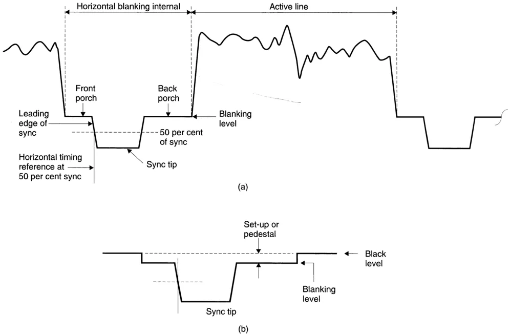
Figure 1.3 (a) Part of a video waveform with important features named. (b) Use of pedestal or set-up.
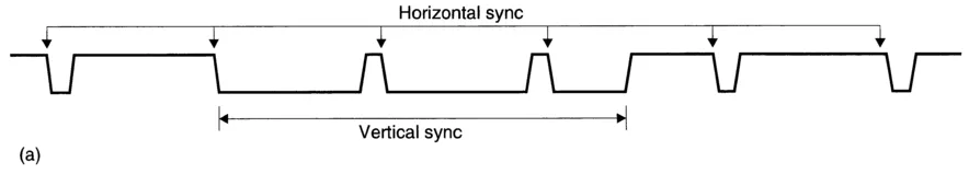
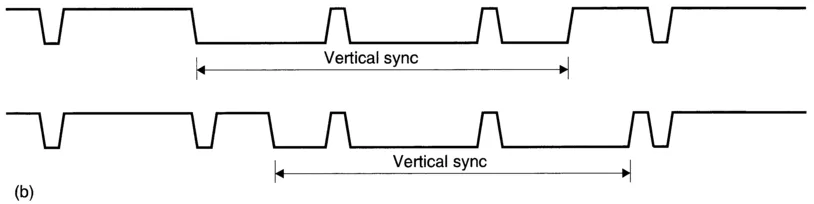
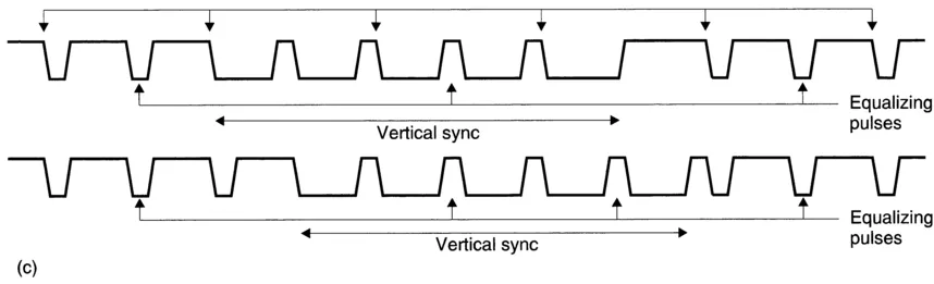
Figure 1.4 (a) A simple vertical pulse is longer than a horizontal pulse, (b) In an interlaced system there are two relationships between Η and V. (c) The use of equalizing pulses to balance the DC component of the signal.
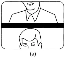
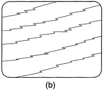
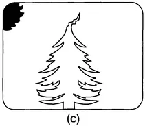
Figure 1.5 (a) Loss of vertical sync causes a frame roll, (b) Loss of horizontal sync causes diagonal picture breakup. (c) A marginal signal may cause tearing.
information, a condition called sync loss occurs, causing the picture to break up. Sometimes only one of the synchronizing signals is defective. If the vertical synchronizing is at fault, the vertical sweep of the CRT beam will begin at the wrong time and the picture will be 'wrapped around' the tube with the bottom at the top and vice versa. The vertical blanking perio...
Table of contents
- Cover
- Half Title
- Dedication
- Title
- Copyright
- Contents
- Preface
- Acknowledgements
- Chapter 1 Video concepts
- Chapter 2 Colour television
- Chapter 3 Digital video
- Chapter 4 Video interfacing
- Chapter 5 Video recording
- Glossary
- Index
Frequently asked questions
Yes, you can cancel anytime from the Subscription tab in your account settings on the Perlego website. Your subscription will stay active until the end of your current billing period. Learn how to cancel your subscription
No, books cannot be downloaded as external files, such as PDFs, for use outside of Perlego. However, you can download books within the Perlego app for offline reading on mobile or tablet. Learn how to download books offline
Perlego offers two plans: Essential and Complete
- Essential is ideal for learners and professionals who enjoy exploring a wide range of subjects. Access the Essential Library with 800,000+ trusted titles and best-sellers across business, personal growth, and the humanities. Includes unlimited reading time and Standard Read Aloud voice.
- Complete: Perfect for advanced learners and researchers needing full, unrestricted access. Unlock 1.4M+ books across hundreds of subjects, including academic and specialized titles. The Complete Plan also includes advanced features like Premium Read Aloud and Research Assistant.
We are an online textbook subscription service, where you can get access to an entire online library for less than the price of a single book per month. With over 1 million books across 990+ topics, we’ve got you covered! Learn about our mission
Look out for the read-aloud symbol on your next book to see if you can listen to it. The read-aloud tool reads text aloud for you, highlighting the text as it is being read. You can pause it, speed it up and slow it down. Learn more about Read Aloud
Yes! You can use the Perlego app on both iOS and Android devices to read anytime, anywhere — even offline. Perfect for commutes or when you’re on the go.
Please note we cannot support devices running on iOS 13 and Android 7 or earlier. Learn more about using the app
Please note we cannot support devices running on iOS 13 and Android 7 or earlier. Learn more about using the app
Yes, you can access Television Fundamentals by John Watkinson in PDF and/or ePUB format, as well as other popular books in Technology & Engineering & Communication Studies. We have over one million books available in our catalogue for you to explore.