- 272 pages
- English
- ePUB (mobile friendly)
- Available on iOS & Android
eBook - ePub
Automotive Computer Controlled Systems
About this book
'Automotive Computer Controlled Systems' explains the fundamental principles of engineering that lie behind the operation of vehicle electronic systems. Having obtained this knowledge, the reader will be able to make full use of the diagnostic equipment which is currently available. The book builds on the concepts contained in Vehicle Electronic Systems and Fault Diagnosis and gives clear steps to fault diagnosis and subsequent repair of the vehicle's electronic systems. The author discusses electronics only within the context of the vehicle systems under consideration, and thus keeps theory to a minimum.
Allan Bonnick has written articles for several transport/vehicle journals and carries out consultancy work for the Institute of Road Transport Engineers. In addition, he has had many years teaching experience and is ideally placed to write this informative guide.
Trusted by 375,005 students
Access to over 1.5 million titles for a fair monthly price.
Study more efficiently using our study tools.
Information
1
Common technology
The aim of this chapter is to review a number of computer controlled vehicle systems that are in current use and to make an assessment of the technology involved that is common to a range of systems. It is this knowledge that is ‘common’ to many systems that enables a vehicle technician to develop a ‘platform’ of skills that will assist in diagnostic work across the spectrum of vehicles, from small cars to heavy trucks.
Subsequent chapters concentrate on aspects of the technology that enable garage technicians to perform diagnostic and other tasks related to the maintenance and repair of modern vehicles. In order to achieve this aim a representative range of systems is examined in outline, so as to give a broad understanding of their construction and mode of operation, as opposed to an ‘in depth’ study of each system. Later chapters look at the individual aspects of each system, such as sensors and the computer (ECM), and provide detailed explanations since the evidence suggests that more detailed knowledge assists in the diagnostic process.
1.1 Common technology
Changes in electronics technology and manufacturing methods take place rapidly and for some years now, microcontrollers (mini-computers) have formed the heart of many of the control systems found on motor vehicles.
Microcontrollers, in common with other computers, contain a control unit and presumably in order to avoid any possible confusion, the ‘black box’ that used to be known as the Electronic Control Unit (ECU) is now commonly referred to as the Electronic Control Module (ECM). In this book, the term electronic control module (ECM) is used when referring to the control module that was formerly known as the ECU.
As vehicle systems have developed it has become evident that there is a good deal of electronic and computing technology that is common to many vehicle electronic systems and this suggests that there is good reason for technicians to learn this ‘common technology’ because it should enable them to tackle diagnosis and repair on a range of vehicles. Indeed, many manufacturers of automotive test equipment are now producing equipment which, when supported by information and data about diagnostic trouble codes (fault codes), provides the knowledgeable technician with the support that should enable him/her to go forward in to the 2000s with a degree of confidence in their ability to maintain and repair modern systems.
We will now look at a representative selection of commonly used modern systems in order to enable us to ‘tease out’ the common elements that it will be useful to learn more about.
1.2 Engine-related systems
The engine systems that are surveyed are those that are most commonly used, namely ignition and fuelling, plus emission control. A major purpose of these system surveys is to identify common ground in order to focus on the components of the systems that can realistically be tested with the aid of reasonably priced tools, rather than the more exotic systems that require specialized test equipment.
By examining three ignition systems it should be possible to pick out certain elements that are commonly used. In the process of examining a number of other systems we shall see that certain basic principles are common to several types of systems that are used on vehicles. In effect, there is a good deal of knowledge that can be transferred across a considerable range of technology.
1.3 Ignition systems
Electronic ignition systems make use of some form of electrical/electronic device to produce the electrical pulse that switches the ignition coil primary current ‘on and off’, so that a high voltage is induced in the coil secondary winding in order to produce a spark in the required cylinder at the correct time.
There are several methods of producing the basic ‘triggering’ pulse for the ignition, but three of these methods are more widely used than the others. It is the ignition systems that are based on the use of these three methods that are now dealt with in some detail.
1.3.1 THE CONSTANT ENERGY IGNITION SYSTEM
Figure 1.1 shows a type of electronic ignition distributor that has been in use for many years. The distributor shaft is driven from the engine camshaft and thus rotates at half engine speed.
Each time a lobe on the rotor (reluctor) passes the pick-up probe a pulse of electrical energy is induced in the pick-up winding. The pick-up winding is connected to the electronic ignition module and when the pulse generator voltage has reached a certain level (approximately 1 V) the electronic circuit of the module will switch on the current to the ignition coil primary winding.
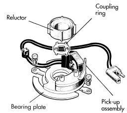
Fig. 1.1 Reluctor and pick-up assembly
As the reluctor continues to rotate, the voltage in the pick-up winding begins to drop and this causes the ignition module to ‘switch of’ the ignition coil primary current; the high voltage for the ignition spark is then induced in the ignition coil secondary winding. The period between switching on and switching off the ignition coil primary current is called the dwell period. The effective increase in dwell angle as the speed increases means that the coil current can build up to its optimum value at all engine speeds. Figure 1.2 shows how the pulse generator voltage varies due to the passage of one lobe of the reluctor past the pick-up probe. From the graphs in this figure may be seen that the ignition coil primary current is switched on when the pulse generator voltage is approximately 1 V and is switched off again when the voltage falls back to the same level. At higher engine speeds the pulse generator produces a higher voltage and the switching-on voltage (approximately 1 V) is reached earlier, in terms of crank position, as shown in the second part of Fig. 1.2. However, the ‘switching-of’ point is not affected by speed and this means that the angle (dwell) between switching the coil primary current on and off increases as the engine speed increases. This means that the build-up time for the current in the coil primary winding, which is the important factor affecting the spark energy, remains virtually constant at all speeds. It is for this reason that ignition systems of this type are known as ‘constant energy systems’. It should be noted that this ‘early’ type of electronic ignition still incorporates the centrifugal and vacuum devices for automatic variation of the ignition timing.
1.3.2 DIGITAL (PROGRAMMED) IGNITION SYSTEM
Programmed ignition makes use of computer technology and permits the mechanical, pneumatic and other elements of the conventional distributor to be dispensed with. Figure 1.3 shows an early form of a digital ignition system.
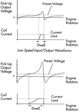
Fig. 1.2 Pick-up output voltage at low and high speeds
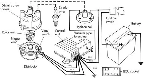
Fig. 1.3 A digital ignition system
The control unit (ECU or ECM) is a small, dedicated computer which has the ability to read input signals from the engine, such as speed, crank position, and load. These readings are compared with data stored in the computer memory and the computer then sends outputs to the ignition system. It is traditional to represent the data, which is obtained from engine tests, in the form of a three-dimensional map as shown in Fig. 1.4.
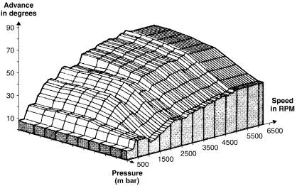
Fig. 1.4 An ignition map that is stored in the ROM of the ECM
Any point on this map can be represented by a number reference: e.g. engine speed, 1000 rpm; manifold pressure (engine load), 0.5 bar; ignition advance angle, 5°. These numbers can be converted into computer (binary) code words, made up from 0s and 1s (this is why it is known as digital ignition). The map is then stored in the computer memory where the processor of the control unit can use it to provide the correct ignition setting for all engine operating conditions.
In this early type of digital electronic ignition system the ‘triggering’ signal is produced by a Hall effect sensor of the type shown in Fig. 1.5.
When the metal part of the rotating vane is between the magnet and the Hall element the sensor output is zero. When the gaps in the vane expose the Hall element to the magnetic field, a voltage pulse is produced. In this way, a voltage pulse is produced by the Hall sensor each time a spark is required. Whilst the adapted form of the older type ignition distributor is widely used for electronic ignition systems, it is probable that the trigger pulse generator driven by the crankshaft and flywheel is more commonly used on modern systems. This is a convenient point at which to examine the type of system that does not use a distributor of the conventional form but uses a flywheel-driven pulse generator.
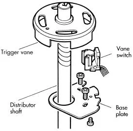
Fig. 1.5 A Hall type sensor
1.3.3 DISTRIBUTORLESS IGNITION SYSTEM
Figure 1.6 shows an ignition system for a four-cylinder engine. There are two ignition coils, one for cylinders 1 and 4, and another for cylinders 2 and 3. A spark is produced each time a pair of cylinders reaches the firing point which is near top dead center (TDC). This means that a spark occurs on the exhaust stroke as well as on the power stroke. For this reason, this type of ignition system is sometimes known as the ‘lost spark’ system.
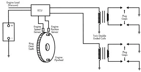
Fig. 1.6 A distributorless ignitio...
Table of contents
- Front Cover
- Half Title
- Title Page
- Copyright
- Contents
- Preface
- Acknowledgements
- Chapter 1 Common Technology
- Chapter 2 The Computer ECM
- Chapter 3 Self-diagnosis and fault codes
- Chapter 4 Diagnostic tools and equipment
- Chapter 5 Sensors
- Chapter 6 Actuators
- Chapter 7 Diagnostic techniques
- Chapter 8 Additional technology
- Appendix
- Index
Frequently asked questions
Yes, you can cancel anytime from the Subscription tab in your account settings on the Perlego website. Your subscription will stay active until the end of your current billing period. Learn how to cancel your subscription
No, books cannot be downloaded as external files, such as PDFs, for use outside of Perlego. However, you can download books within the Perlego app for offline reading on mobile or tablet. Learn how to download books offline
We are an online textbook subscription service, where you can get access to an entire online library for less than the price of a single book per month. With over 1.5 million books across 990+ topics, we’ve got you covered! Learn about our mission
Look out for the read-aloud symbol on your next book to see if you can listen to it. The read-aloud tool reads text aloud for you, highlighting the text as it is being read. You can pause it, speed it up and slow it down. Learn more about Read Aloud
Yes! You can use the Perlego app on both iOS and Android devices to read anytime, anywhere — even offline. Perfect for commutes or when you’re on the go.
Please note we cannot support devices running on iOS 13 and Android 7 or earlier. Learn more about using the app
Please note we cannot support devices running on iOS 13 and Android 7 or earlier. Learn more about using the app
Yes, you can access Automotive Computer Controlled Systems by Alan Bonnick,Allan Bonnick in PDF and/or ePUB format, as well as other popular books in Technology & Engineering & Automotive Transportation & Engineering. We have over 1.5 million books available in our catalogue for you to explore.