![]()
I HVAC control systems
I. I Basic concepts
It is not frequently acknowledged that heating, ventilating and air conditioning (HVAC) systems present one of the most challenging situations to deal with from the point of view of control. Swings in day-to-day, week-to-week and season-to-season energy demand together with the infinitely complex combination of user needs at the human interface contribute to a highly non-stationary ‘environment’ within which control takes place. It is little wonder then that much of HVAC control is about compromise; a compromise that usually amounts to reasonable comfort at minimum energy use and cost.
HVAC control in common with all process system control requires the governance of two distinct actions; those of switching or ‘enabling’ and regulating or ‘adjustment’. Switching in the majority of applications amounts to ensuring that the plant is available at certain times of the day (generally, those times of the day in which a building is in use). This will be essentially clock-based, occupancy-sensor-based or indeed based on some other logical two-state condition such as an alarm state. Regulation, which is what this book in essence is about, amounts to ensuring that the plant capacity is matched to the demands placed upon the system.
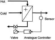
Let us consider some basic concepts of HVAC control. Figures 1.1, 1.2 and 1.3 show three quite contrasting ways of controlling the output of a simple heat exchanger. The actions of these three systems are quite different.
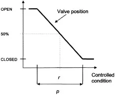
Under analogue control, the controller positions the valve anywhere between fully open and fully closed (Figure 1.4) using a smooth continuous signal from the controller. Control is defined in terms of a reference condition or set point (r) and a proportional band (p) which represents the range of the controlled condition for which the output of the controller is proportional. Figure 1.4 for instance shows that the valve will settle at the set point at 50% of its range and, during fluctuating conditions, the temperature will drift either side of the set point until control action restores its value at the latter. This was the predominant method of HVAC system control until the early 1980s and still exists today in the form of mechanical direct-acting control devices. For example, the ‘thermostatic’ radiator valve (TRV) is one case of this type of control.
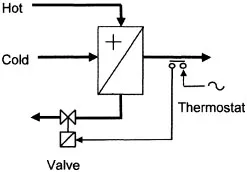
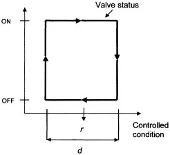
Under thermostatic control, control is a two-state process. The thermostat is a switching device and positions the valve periodically in either a fully closed position or a fully open position; there are no in-betweens. Control action is defined in terms of a set point and dead band (d) which represents a band of inactivity the limits of which form switching events (Figure 1.5). This method of control is widespread; there are numerous examples in the home such as the domestic iron and the portable electric fan heater. It has the advantage of achieving reasonably effective control with great simplicity but the disadvantages of a fluctuating controlled condition (within the limits of the dead band) and the frequent switching of equipment which in some cases can cause excessive wear on components. For these reasons it is not used commonly in the UK for conventional HVAC control but is used widely for domestic heating, unitary air conditioners and small-scale atmospheric boilers.
Figure 1.1 Analogue control.
Figure 1.2 Thermostatic control.
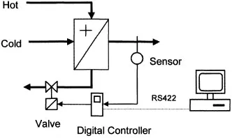
Figure 1.3 Digital control.
Figure 1.4 Proportional control action.
Figure 1.5 Thermostatic control action.
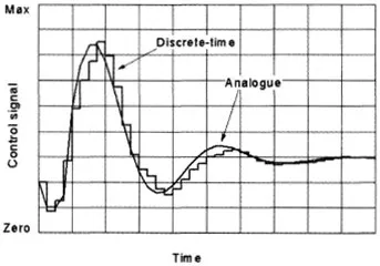
Figure 1.6 Typical analogue and digital control signals.
Under digital control, control action takes place at discrete points in time, each point separated by a time interval, T. The valve position will assume a position anywhere between fully open and fully closed according to a calculation carried out by the controller at each discrete point in time (Figure 1.6). In between these times, control action freezes. Digital control offers enormous flexibility particularly when the controller forms part of a network linked to a supervisory computer. The controller can be designed as a ‘stand-alone’ for the specific task, merely requiring setting up and adjustment for precise plant conditions – application-specific controller (ASC) – or freely programmable for whatever task is intended – universal controller (UC). Alternatively, parametric control decisions and actions can be performed by the central supervising computer with local control decision-making and signal management carried out at the plant ‘level’ by programmable intelligent outstations.
Whether networked or stand-alone application-specific, this type of control is now the predominant method for conventional non-domestic HVAC systems and plant.
We will now move on to take a look at some of the established applications of HVAC control.
1.2 HVAC control strategies
Constant-volume air handling
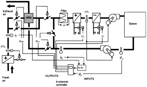
Figure 1.7 shows the general arrangement for the four-channel control of an air handling system serving one zone in which the four channels control, in sequence, heating → heat recovery → fresh air (‘free’ cooling) → chilled water-based cooling.
Note that the heat recovery is optional and would only tend to be used in this application when the minimum fresh air in total air handled is high due, for instance, to high occupancy density in the zones served by the air handling system. Note also that the controlled condition becomes supply air temperature in situations where the air handling system’s function is to provide pre-conditioned air to rooms or zones which themselves have local sequenced heating and cooling control.
Operation The controlled condition is the space temperature, θr. It is usual to measure this in the return air duct, provided that there are no intervening heat gains, such as light fittings, in the return air path. The return air will be well-mixed and the temperature sensor at the higher in-duct air velocities will tend to be more responsive than in the comparatively still air conditions of the space. For space or room temperature control, the manipulated variables will be:
• the flow rate of heating water by means of diverting control valve, VH;
• the proportion of direct and bypass air at the heat recovery heat exchanger, HRX, by means of face and bypass dampers, DHR;
Figure 1.7 Control for constant-volume air handling.
• the proportion of fresh and recirculating air at the mixing dampers, DFA; and
• the flow rate of chilled water by means of diverting control valve, VC.
During very warm summer weather, the fresh air damper will be fully open and the heat recovery face and bypass dampers positioned for full bypass in order to achieve ‘free cooling’. The limit to free cooling is reached when the fresh air intake enthalpy exceeds the enthalpy of the return air at a point downstream of the return air fan, a condition that takes place during the peak summer season in the UK though will often be short-lived. At this condition, it is necessary to signal to the fresh air damper a return to its minimum position and for the heat recovery face and bypass dampers to reposition so as to allow full heat recovery (which will now, in effect, provide pre-cooling of the fresh air from the cool building exhaust air). Enthalpy sensors he and hf provide this and most control system manufacturers will permit additional plug-in modules for their multi-channel controllers to achieve these summer reset conditions. In the arrangement shown, when he – hf produces a negative signal, the reset conditions described are enacted.
To provide frost protection, there are two features. Firstly, the heat recovery heat exchanger (if present) is protected from icing during very cold weather by an upstream frost coil on the fresh air side. Because of the highly temporal nature of calls on the frost coil, a simple thermostatic control through a two-position two-port control valve is usually sufficient. Frost thermostat FTH provides for this. Secondly, should any primary heating plant such as central boilers or pumps fail, all coils in the arrangement are vulnerable to freezing of their respective water contents during very cold weather, especially the frost coil itself. To provide last-line protection against this, frost thermostat FTF acts to trip both fans (a further precaution might be to provide a two-position isolating damper at the fresh air intake which coincidentally closes in these conditions thereby eliminating any natural draught through the plant when idle). Typically, ...