Electronic and Electrical Servicing – Level 3 follows on from the Level 2 book and covers the more advanced electronics and electrical principles required by service engineers servicing home entertainment equipment such as TVs, CD and DVD machines, as well as commercial equipment including PCs.
All the core units of the Level 3 Progression Award in Electrical and Electronics Servicing (Consumer/Commercial Electronics) from City & Guilds (C&G 6958) are covered. The book also offers a fully up-to-date course text for the City & Guilds 1687 NVQ at Level 3.
The book contains numerous worked examples to help students grasp the principles. Each chapter ends with review questions, for which answers are provided at the end of the book, so that students can check their learning.
Units covered: Unit 1 – Electronic principles Unit 2 – Test and measurement Unit 3 – Analogue electronics Unit 4 – Digital electronics
Ian Sinclair has been an author of market-leading books for electronic servicing courses for over 20 years, helping many thousands of students through their college course and NVQs into successful careers. Now with a new co-author, John Dunton, the new edition has been brought fully up-to-date to reflect the most recent technical advances and developments within the service engineering industry, in particular with regard to television and PC servicing and technology.
1. Demonstrate an understanding of reactance, resonance, transformers and transfer and the practical application of these components and circuits
2. Demonstrate an understanding of semi-conductor devices, displays and transducers and the practical applications of these components.
26
Sine wave driven circuits
Capacitors and inductors in direct current (d.c.) circuits cause transient current effects only when the applied voltage changes. In an alternating current (a.c.) circuit this is a continuous process. Capacitors in such a circuit are therefore continually charging and discharging, and inductors are continually generating a changing back-electromotive force (emf). Circuits containing resistors, capacitors and inductors are described as complex circuits and an alternating voltage will exist across each component proportional to the magnitude of current flowing through it so that a form of Ohm’s law still applies.
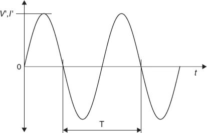
In the explanation that follows, the symbols V′ and I′ are used to mean peak a.c. values (Figure 26.1) of alternating signals. Root mean square (r.m.s.) values are represented by Vrms and Irms; that is, Irms = I′/
. The symbols v and i represent instantaneous values of a.c. signals and V and I will have their usual meaning of d.c. values. So, we may write v = V′ sin (2πft).
Figure 26.1 The peak value and period of a sine wave of voltage or current
For a resistor in an a.c. circuit, V′ =R × I′ and the value of resistance found from the variant form of this equation, R =
, is the same as the d.c. value, V/I. In a capacitor or an inductor, the ratio V′/I′ is called reactance, with the symbol X. Because this is a ratio of volts to amperes, the same units Ω (ohms) are used as used to express d.c. resistance, but it must be remembered this is a frequency-dependent reactance and not a resistance.
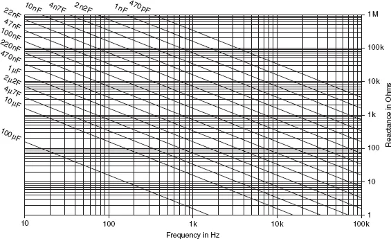
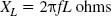
A capacitor may, for example, have a reactance of only 1 KΩ at a given frequency, but a d.c. resistance that is unmeasurably high. An inductor may have a d.c. resistance of 10 ohms, but a reactance of 5 KΩ or more. The reactance of a capacitor or an inductor is not a constant quantity, but depends on the frequency of the applied signal. A capacitor, for example, has a very high reactance to low-frequency signals and a very low reactance to high-frequency signals, as indicated in Figure 26.2.
Figure 26.2 Chart of capacitive reactance at audio frequencies
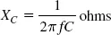
The reactance of a capacitor V′/I′ can be calculated from the equation:
where f is the frequency of the signal in Hz and C is the capacitance in farads. Figures 26.2 and 26.3 show the values of capacitive reactance for a range of different capacitors calculated for a range of frequencies. These charts are intended as a guide so that you can quickly estimate a reactance value without the need to make the calculations.
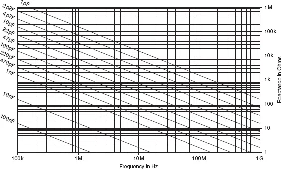
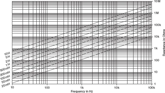
The reactance of an inductor varies in the opposite way, being low for low-frequency signals and high for high-frequency signals. Its value can be calculated from the equation:
where f is the frequency in Hz and L is the inductance in henries. Figures 26.4 and 26.5 show the values of inductive reactance which are found at various frequencies.
Figure 26.3 Chart of capacitive reactance at radio frequencies
Figure 26.4 Inductive reactance at audio frequencies
Figure 26.5 Inductive reactance at radio frequencies
Note: inductors are now less common in circuits other than power supply and radio (transmission and reception) applications. The increasing use of integrated circuits (ICs) and digital circuitry has made the use of inductors unnecessary in a very wide range of modern applications.
Practical 26.1
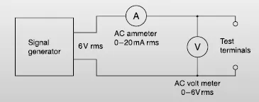
Connect the circuit shown in Figure 26.6. If meters of different ranges have to be used, changes in the values of capacitor and inductor will also be necessary. The signal generator must be capable of supplying enough current to deflect the current meter which is being used.
Figure 26.6 Circuit for practical
Connect a 4.7 μF capacitor between the terminals, and set the signal generator to a frequency of 100 Hz. Adjust the output so that readings of a.c. voltage and current can be made. Find the value of V′/I′’ at 100 Hz.
Repeat the measurements at 500 Hz and at 1000 Hz. Tabulate values of XC = V′/I′ and of frequency f.
Now remove the capacitor and substitute a 0.5 H inductor. Find the reactance at 100 Hz and 1000 Hz as before, and tabulate values of XL = V′/I′ and of frequency f.
Next, either remove the core from the inductor or increase the size of the gap in the core (if this is possible), and repeat the measurements. How has the reactance value been affected by the change?
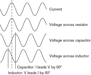
There is another important difference between a resistance and a capacitive or inductive reactance and this can be demonstrated as follows. With the aid of a double-beam oscilloscope, the a.c. waveform of the current flowing through a resistor and the voltage developed across it can be displayed together (Figure 26.7). This shows that the two waves coincide, with the peak current coinciding with the peak voltage, etc. If this experiment is repeated with a capacitor or an inductor in place of the resistor, you will see from the figure that the waves of current and voltage do not coincide, but are a quarter-cycle (90˚) out of step.
Figure 26.7 Phase shift caused by a reactance
Comparing the positions of the peaks of voltage and of current, you can see that:
• For a capacitor, the current wave leads (or precedes) the voltage wave by a quarter-cycle.
• For an inductor, the voltage wave leads the current wave also by a quarter-cycle.
An alternative way of expressing this is that, for a capacitor, the voltage wave lags (or arrives after) the current wave by a quarter-cycle, and for an inductor, the current wave lags the voltage wave by a quarter-cycle.
The amount by which the waves are out of step is usually defined by the phase angle. The current and voltage waves are 90° out of phase in a reactive component such as a capacitor or an inductor.
A useful way to remember the phase relationship between the current and voltage is the word C-I-V-I-L, meaning C–I leads V; V leads I–L. The letters C and L are used to denote capacitance and inductance, respectively.
If we take a few measurements on circuits containing reactive components we can see that the normal circuit laws used for d.c. circuits cannot be applied directly to a.c. circuits.
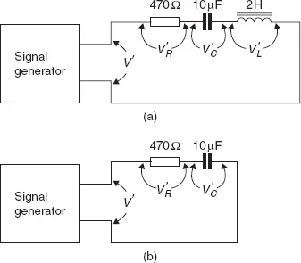
Consider, for example, a series circuit containing a 10 μF capacitor C, a 2 H inductor L and a 470 ohm resistor R, as in Figure 26.8(a). With 10 V a.c. voltage, V′ at 50 Hz applied to the circuit, the a.c. voltages across each component can be measured and added together: V′c + V′L + V′R. You will find that these measured voltages do not add up to the voltage V′ across the whole circuit.
Figure 26.8 Series circuits: (a) RLC, and (b) RC circuit for practical example
Practical 26.2
Connect the circuit shown in Figure 26.8(b). Use either a high-resistance a.c. voltmeter or an oscilloscope to measure the voltage V′R across the resistor and the voltage V′C across the capacitor. Now measure the total voltage V′ and compare it with V′R + V′C.
The reason why the component voltages in a complex circuit do not add up to the circuit voltage when a.c. flows through it is due to the phase angle between voltage and current in the reactive component(s). At the peak of the current wave, for example, the voltage wave across the resistor will also be at its peak, but the voltage wave across any reactive component will be at its zero value. Measurements of voltage cannot, however, indicate phase angle. They can only give the r.m.s. or peak values for each component, and the fact that these values do not occ...
Table of contents
Cover
Title
Copyright
Contents
Preface to the second edition – level 3
Acknowledgements
Unit 1
Unit 2
Unit 3
Unit 4
Answers to multiple-choice questions
Index
Frequently asked questions
Yes, you can cancel anytime from the Subscription tab in your account settings on the Perlego website. Your subscription will stay active until the end of your current billing period. Learn how to cancel your subscription
No, books cannot be downloaded as external files, such as PDFs, for use outside of Perlego. However, you can download books within the Perlego app for offline reading on mobile or tablet. Learn how to download books offline
Perlego offers two plans: Essential and Complete
Essential is ideal for learners and professionals who enjoy exploring a wide range of subjects. Access the Essential Library with 800,000+ trusted titles and best-sellers across business, personal growth, and the humanities. Includes unlimited reading time and Standard Read Aloud voice.
Complete: Perfect for advanced learners and researchers needing full, unrestricted access. Unlock 1.4M+ books across hundreds of subjects, including academic and specialized titles. The Complete Plan also includes advanced features like Premium Read Aloud and Research Assistant.
Both plans are available with monthly, semester, or annual billing cycles.
We are an online textbook subscription service, where you can get access to an entire online library for less than the price of a single book per month. With over 1 million books across 990+ topics, we’ve got you covered! Learn about our mission
Look out for the read-aloud symbol on your next book to see if you can listen to it. The read-aloud tool reads text aloud for you, highlighting the text as it is being read. You can pause it, speed it up and slow it down. Learn more about Read Aloud
Yes! You can use the Perlego app on both iOS and Android devices to read anytime, anywhere — even offline. Perfect for commutes or when you’re on the go. Please note we cannot support devices running on iOS 13 and Android 7 or earlier. Learn more about using the app
Yes, you can access Electronic and Electrical Servicing - Level 3 by John Dunton in PDF and/or ePUB format, as well as other popular books in Technology & Engineering & Civil Engineering. We have over one million books available in our catalogue for you to explore.