Since it was first published in 1962, The Theory and Practice of Seamanship has been continuously revised, culminating in this 11th edition. This new edition includes an updated section on 'Regulations for Prevention of Collision at Sea' as well as a new Author's Note. It has been widely praised and is the standard work on the subject.
- 544 pages
- English
- ePUB (mobile friendly)
- Available on iOS & Android
eBook - ePub
Theory and Practice of Seamanship XI
About this book
Trusted by 375,005 students
Access to over 1.5 million titles for a fair monthly price.
Study more efficiently using our study tools.
Information
CHAPTER I
THE ANCHOR
THE ADMIRALTY PATTERN, STOCKED OR COMMON ANCHOR
This anchor is illustrated in Fig. 1.1 together with the names of the various parts. It is fitted with a stock, which should be of an approved design and weigh one-quarter of the specified weight of the remainder of the anchor. It is renowned for its excellent holding qualities, and even today some designs of patent stockless anchors are no more efficient, so far as holding properties are concerned, than the common anchor of one hundred years ago, assuming anchors equal in weight. It is no longer required to be carried on merchant ships. When the anchor strikes the sea-bed the stock, being longer and heavier than the arms, assumes the horizontal position as soon as the anchor is stressed, thus causing the lower arm and fluke to become embedded. The stock gives the anchor great stability, i.e. it prevents it from rotating under heavy load or a stress applied other than in line with the shank. The anchor will turn in a horizontal plane quite easily as a ship swings with the tidal stream or wind. There are no moving parts to become choked with sea-bed material, so that should the anchor be accidentally broken out of its holding position it remains efficient for re-anchoring.
The upper fluke, which protrudes from the sea-bed, contributes no holding power and may become fouled by the cable as the ship swings. Further, in very shallow water, or where the sea-bed dries out, small craft may become impaled on this fluke. The common anchor is difficult to stow with the stock in position. In merchant ships it is usually found as a light (non-compulsory) kedge anchor with the stock stowed parallel with the shank, or as a lifeboat anchor. As a kedge anchor it is likely to weigh up to 2 tonnes (2 tons), dimensions for this weight being roughly 3·9 m (12 ft 6 in) overall length; 3·7 m (12 ft) length of stock, and 2·5 m (8 ft) width of arms.
The steel common anchor of today has a holding power of roughly three to four times its weight, depending upon the sea-bed. It is of sur prising historical interest to note that Admiral Lord Nelson’s anchor (H.M.S. Victory), with its buoyant oak stock, had a holding power of 2·8 times its weight. Efficiency improvements have therefore been small since then, and are only just developing.
The spheres or enlargements at the stock extremities serve two purposes: they assist rotation of the anchor when biting, and prevent, to a certain extent, sinking of the stock into the sea-bed when it is providing stability under load.
THE PATENT STOCKLESS ANCHOR
This anchor is also illustrated in Fig. 1.1. It has no stock, and can therefore be hove right home into the hawse pipe, quickly secured, and is ready for instant letting go. The entire head, including the arms and flukes, is able to pivot about the end of the shank. Its angle of rotation is limited by stops to 45 degrees from the axis of the shank. In some designs this angle is as low as 30 degrees. The head must weigh at least 60% of the total weight of the anchor.
If it strikes the sea-bed with the flukes vertical, their tripping palms chafe the surface and start rotation of the arms. The anchor has good holding power, in the region of three to four times its weight in efficient holding ground, but has a moving part which can become choked with sea-bed material. This may well cause the flukes to fail to re-trip should the anchor be broken out of its holding position. For this reason, when anchoring for some time, it is a good practice to regularly weigh the anchor and sight it. This applies particularly on sandy and muddy sea-beds, and an opportunity is afforded to hose the anchor using a high-pressure water jet. Some shipping companies insist upon this being done.
Having no stock this type of anchor is unstable, and when dragging under heavy load is liable to rotate through 180 degrees. If the flukes fail to re-trip, any holding power remaining is due entirely to weight and, in turn, friction. The size of the flukes is a direct measure of the holding properties.
Disadvantages such as are noted above are generally overlooked in the light of its easy stowage. It is an ideal (non-compulsory) stream anchor for vessels fitted with stern hawse pipes.
Both the stocked and the stockless anchor may have a ring secured to the shank at the anchor’s centre of gravity. This is the gravity band.
The most common types found in the Merchant Service are the Byer’s, Hall’s, and Taylor’s patent stockless anchors. Two are carried as bower anchors in the hawse pipes and a third is carried as a spare or sheet anchor. Typical dimensions of a 5-tonne (5 ton) anchor would be 3·5 m (11·3 ft) overall length; 2·1 m (7 ft) extreme length of head; 1 m (3 ft) measured in side elevation across tripping palms of one fluke and 1·7 m (5 ft 8 in) from fluke tip to crown. Tests at the Admiralty Experimental Works have shown that:
- Holding power is raised by increasing the fluke area.
- It is also increased by having smooth, unribbed flukes.
- A holding power of ten times the weight can be obtained.
- Stability can be effected by using stabilising fins.
- A dihedral surface on the flukes gives a greater holding power.
- Such a surface is more easily obtained with hollow flukes.
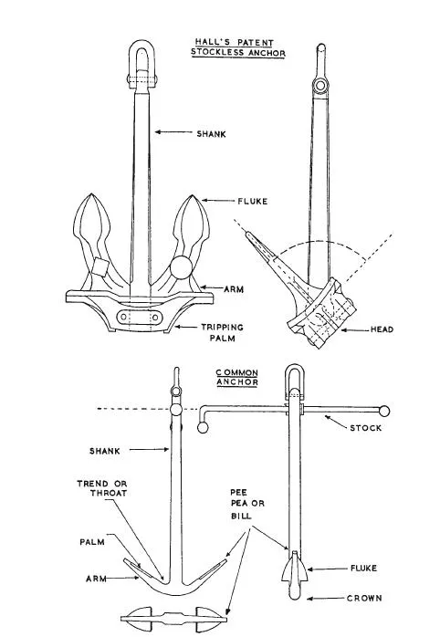
FIGURE 1.1
The stockless anchor with tumbling flukes was introduced in 1840, and since that date effective changes in design have been negligible. In the latter half of the nineteenth century the Admiralty conducted tests in order to select the most efficient type, but little was done to improve efficiency.
Tests were reintroduced in 1943 after much complaint by personnel during the war of the inefficiency of anchors. After four or five modifications to a prototype, a new design was effected and is known as the
ADMIRALTY CAST ANCHOR TYPE A.C.14
This anchor is fully illustrated in Fig. 1.2 and is now accepted as a merchant ship anchor. It was tested in practically every type of sea-bed, including blue clay (a poor holding ground for stockless anchors), sand, shingle, soft mud, and hard rock covered with a thin layer of silt. These proved it to be an anchor of great stability, having stabilising fins at the head extremities. It was able to change direction rapidly and without loss of pull. In almost all types of sea-bed it had a holding power of two and a half to three times that of a stockless standard anchor of equal weight.
Listed below are some of the test results using a 2·5-tonne (52-cwt) Type A.C.14 anchor with hollow flukes, and a 5·25-tonne (5 1/4-ton) standard stockless anchor in the same bed. The figures compared are maximum holding powers in terms of weight.
| Sea-bed | A.C.14 | Standard slockless |
| Red clay, sand, shingle, rocks | 10.0 | 3.9 |
| Blue clay, thin layer of mud, sand. | 13.6 | 3.1 |
| Soft mud . . . . | 8.2 | 1.6 |
| Flat, smooth rock, thin layer of silt | 2.8 | 1.9 |
In the first three cases, the lighter anchor developed the greater pull in tonnes—one to two times that of the heavier anchor. In the fourth case, however, the heavier anchor was superior in this respect and indicates that a minimum weight must be maintained for anchors fitted to ships likely to have to attempt anchoring in practically impenetrable sea-beds. Danforth-Jackson have developed the Stokes anchor which resembles the A.C.14 anchor. When the prototype anchor was tested in holding ground composed of large gravel, sand and clay, it was found to have a holding power of 15·2 times the weight compared with only 4·4 for a standard stockless anchor of similar weight. This anchor has been granted a 25% reduction in Rule weight by Lloyd’s Classification Society. The flukes are made as thin as possible to ensure maximum penetration of the sea-bed. The normal Danforth anchor which has a straight stock passing through the tumbling flukes gives a holding power of 14·2 times the weight in the same ground. This anchor, despite its efficiency, is still largely used only in small craft. Its stowage properties are good.
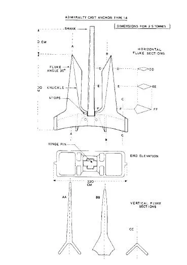
FIGURE 1.2
CHAIN CABLE
This may be made of wrought iron, forged mild steel, cast steel, or special-quality forged steel. Wrought iron is weaker than the other three materials and is more difficult to obtain nowadays. Forged steel is some 40% stronger, and therefore a smaller, lighter (by about 12 1/2%) cable is permissible. For example, a vessel may be required to carry either a wrought-iron cable of 70 mm (2 13/16 in) in size, or a special-quality steel cable of 61 mm (2 7/16 in) in size. Over a length of 22 shackles of cable, this affords a saving in weight of 17 tonnes (tons).
The size of chain cable is measured by the diameter of the bar from which the link is made (Fig. 1.3). Studs are fitted to prevent kinking and longitudinal stretching of the links. They are also said to provide an increase in strength of up to 15%, compared with open-link chain of the same size. The studs are sometimes fitted into the link under a very high pressure (46t/cm2), but one manufacturer, at least, moulds his link and stud in one piece. In wrought-iron cable the studs are welded in place.
Anchor and joining shackles, and other cable fittings, are ordered for the size of the cable for which they are intended. The following breaking and proof stress formulae are a rough guide, but are by no means accurate throughout the range, of size. The symbol D represents the size of the cable in mm, and the results are in tonnes.
| Material | Proof stress | Breaking stress | |
| Wrought iron | . . . . | D2/36 | D2/26 |
| Special steel | . . . . | D2/24 | D2/17 |
The minimum weight of special-quality steel cable in kilogrammes per metre is roughly given by the formula D2/50.
Cable is made in lengths of 27·5 m (15 fathoms) called shackles—the Americans call them shots. They are connected by lugged or lugless joining shackles (Fig. 1.3 and 1.4). When using a lugged joining shackle, the lugs are too big to pass through a common link and are therefore con nected to an open link which is unstudded and known as the end link. Having no stud, it is weaker than the common links, and is therefore enlarged. This will not fit a common link either, and the two are therefore connected by an enlarged studded link called an intermediate link. Fig. 1.3 shows these links, and the joining shackle, together with their size relative to the common link. The sizes are approximate but near enough for practical purposes. The length of a link is 6D and its breadth 3·6D.
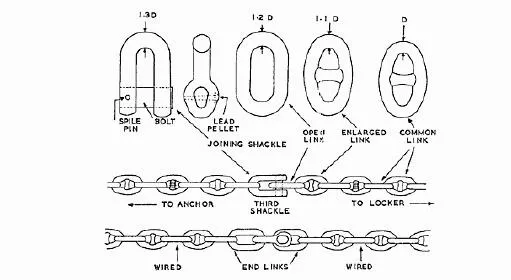
FIGURE 1.3
LUGGED JOINING SHACKLES
These are closed by means of a bolt. This is secured in place by driving a brass or tinned-steel pin, having a taper of one in sixteen, through the bolt and one lug. When the pin is firmly home a lead pellet is hammered into the small, reverse-dovetailed chamber above the large end of the pin. The depth of this chamber is equal to the large diameter of the pin, and the total amount of dovetailing is equal to the half-depth.
The pin is called the spile pin, and in some cases, particularly in the first one or two joining shackles, is made of ash or male (solid) bamboo. This enables the bolt to be removed by hammering its unlipped end, thus shearing the wooden pin. If metal, the spile pin is removed by punching its smaller end, the lead pellet being knocked out with the pin. Before fitting a new pellet, the remains of the old one must be reamed out of the dovetailing. Anchor shackles have a metal spile pin. Older ones may be found having a forelock.
These shackles are fitted to the cable with the bow end facing outboard. This is done so that the lugs do not foul projections as the cable runs out. Anchor shackles are fitted in the reverse direction because they are unlikely to foul as the anchor is let go, and the lugs will not foul a projection as the anchor is hove home.
The bolt should be well smeared with white lead and tallow or similar compound when assembling, otherwise it may become frozen in position. In such a case the shackle should be heated so that the lug expands more quickly than that part of the bolt within it. This can be done with a blowlamp in the absence of dockyard equipment. A very old method was to light a fire beneath the shackle using tar and oakum.
LUGLESS JOINING SHACKLES
These are made of non-c...
Table of contents
- COVER PAGE
- TITLE PAGE
- COPYRIGHT PAGE
- FIGURES
- PLATES
- AUTHOR’S NOTE
- ACKNOWLEDGMENTS
- TABLE OF CONVERSIONS (WITH BS ABBREVIATIONS)
- CHAPTER I: THE ANCHOR
- CHAPTER II: MOORING
- CHAPTER III: THE PRINCIPLES OF SHIP HANDLING
- CHAPTER IV: PRACTICAL SHIP HANDLING
- CHAPTER V: ICE
- CHAPTER VI: LIFE-SAVING AND DISTRESS
- CHAPTER VII: DAMAGE CONTROL
- CHAPTER VIII: STRANDING AND BEACHING
- CHAPTER IX: EMERGENCIES
- CHAPTER X: TOWING
- CHAPTER XI: FIRE
- CHAPTER XII: DRYDOCKING AND LOADLINES
- CHAPTER XIII: THE OFFICER OF THE WATCH
- CHAPTER XIV: THE SAFETY OF NAVIGATION
- CHAPTER XV: LIFTING GEAR
- CHAPTER XVI: ROPE AND CANVAS
- CHAPTER XVII: DECK APPLIANCES
- CHAPTER XVIII: THE SHIP’S BOAT
- CHAPTER XIX: THE DEPARTMENT OF TRANSPORT ORAL EXAMINATION—FOREIGN-GOING
Frequently asked questions
Yes, you can cancel anytime from the Subscription tab in your account settings on the Perlego website. Your subscription will stay active until the end of your current billing period. Learn how to cancel your subscription
No, books cannot be downloaded as external files, such as PDFs, for use outside of Perlego. However, you can download books within the Perlego app for offline reading on mobile or tablet. Learn how to download books offline
Perlego offers two plans: Essential and Complete
- Essential is ideal for learners and professionals who enjoy exploring a wide range of subjects. Access the Essential Library with 800,000+ trusted titles and best-sellers across business, personal growth, and the humanities. Includes unlimited reading time and Standard Read Aloud voice.
- Complete: Perfect for advanced learners and researchers needing full, unrestricted access. Unlock 1.5M+ books across hundreds of subjects, including academic and specialized titles. The Complete Plan also includes advanced features like Premium Read Aloud and Research Assistant.
We are an online textbook subscription service, where you can get access to an entire online library for less than the price of a single book per month. With over 1.5 million books across 990+ topics, we’ve got you covered! Learn about our mission
Look out for the read-aloud symbol on your next book to see if you can listen to it. The read-aloud tool reads text aloud for you, highlighting the text as it is being read. You can pause it, speed it up and slow it down. Learn more about Read Aloud
Yes! You can use the Perlego app on both iOS and Android devices to read anytime, anywhere — even offline. Perfect for commutes or when you’re on the go.
Please note we cannot support devices running on iOS 13 and Android 7 or earlier. Learn more about using the app
Please note we cannot support devices running on iOS 13 and Android 7 or earlier. Learn more about using the app
Yes, you can access Theory and Practice of Seamanship XI by Graham Danton in PDF and/or ePUB format, as well as other popular books in Technology & Engineering & Business General. We have over 1.5 million books available in our catalogue for you to explore.