Carpentry and Joinery 3 is the third in a series of three books, which together provide an authoritative and thoroughly practical guide to carpentry and joinery for students following City & Guilds and CITB courses, NVQ candidates, and students working towards an Institute of Carpenters qualification. This book is also ideal for a wide range of amateur and professional woodworkers.
Volume 3 builds on the fundamental knowledge introduced in volume 1, and accompanies volume 2 with coverage of additional advanced topics and procedures, including working with particular door and window types. The reader is shown how to apply the basic theory introduced in volume 1 to actual carpentry and joinery practice in a highly illustrated, easily accessible text.
This second edition has been fully updated in line with changes to the Building Regulations and current legislation, the third edition also incorporates developments in current best practice, with a comprehensive match to the latest qualifications in Wood Occupations.

- 416 pages
- English
- ePUB (mobile friendly)
- Available on iOS & Android
eBook - ePub
Carpentry and Joinery 3
About this book
Trusted by 375,005 students
Access to over 1 million titles for a fair monthly price.
Study more efficiently using our study tools.
Information
Subtopic
Civil Engineering| 1 | Prefabricated Buildings |
In many situations, prefabricated timber buildings provide an alternative to traditional (masonry) on-site building.
The components which go towards constructing load-bearing walls, and in some cases the floors and roof, are either fully or partially prefabricated. This process can be carried out on site, but in the UK it will almost certainly be done within a factory, where conditions can be controlled and operatives are not hindered by unreliable weather.
Once the on-site foundations have been constructed, the pre-made units or components can be delivered and erected as and when required.
The main advantage of prefabrication compared with fabrication on site is that the superstructure can be erected very quickly to form a weather-resistant envelope, thereby providing a sheltered environment for greater work continuity across the building trades.
Whether the building is to be demountable (capable of being dismantled and reassembled elsewhere) or a permanent fixture will mainly depend on its use and size.
1.1 Small Demountable Timber-Framed Structures
Structures of this type may be used as site huts for temporary accommodation. Although more commonly used these days, prefabricated, proprietary modular units are generally employed. These not only provide temporary accommodation for site personnel and their equipment, but also offer storage space for perishable and/or valuable building materials.
However, garden sheds and summer-houses are usually constructed as timber-frame structures.
The floor, sides, and roof may consist of one or more panels. These panels are joined together at their corners and along their length with coach bolts or similar devices capable of cramping and holding the joint temporarily or permanently secure.
It is common practice to make panels to a modular size (say multiples of 500 mm or 600 mm) to suit board or timber lengths – panels can then be interchangeable as shown in Fig. 1.1a. In this way (provided that structural stability is not affected), a door or window can be sited to suit almost any situation.
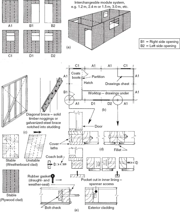
Fig. 1.1 Timber-framed wall panels.
Note: Shutters over windows optional
Figure 1.1b shows a possible floor layout of a site hut using six panel variations. Except for the partition, the order for the wall panels might read as follows in Table 1.1.
Table 1.1 Order of wall panels
Site hut (see Fig. 1.1) – wall panels 1.2 m (type 600 module)
Site hut (see Fig. 1.1) – wall panels 1.2 m (type 600 module)
| Panel code | Number |
| A1 | 7 |
| B1 | 1 |
| B2 | 0 |
| C1 | 2 |
| D1 | 1 |
| D1 | 1 |
| Total number of panels | 12 |
1.1.1 Construction and Erection
1.1.1.1 Walls
Wall panel sizes vary, being often influenced by:
- the type of building;
- the size and type of cladding;
- transportation;
- handling techniques, for example, by hand or machine.
The structural strength of a panel is derived from the row of vertical members called ‘studs’. Studding is trimmed at the top by a head-piece, and at the bottom with a sole-piece of the same sectional size. All the joints are nailed.
If panels are to be externally clad with a strip material, e.g. weather-board, etc. (see Chapter 2), the framework should be diagonally cross-braced to prevent ‘racking’ (lateral movement) as shown in Fig. 1.1c.
Diagonal noggings of solid timber or perforated galvanized-steel strapping, let into and nailed on to studding under the cladding, can be used as bracing as shown in Fig. 1.1c. Diagonal cross-bracing is not always necessary when the frames are clad with a sheet material – an exterior cladding of exterior-grade plywood can provide very good resistance to racking.
Figure 1.1d shows how panels can be joined together. If the panels are lined on the inside – possibly to house some form of insulation material between the studding – pockets should be left to allow access to coach bolts, etc. A more effective joint can be made by introducing a rubber-type gasket between the edges of the panels as shown in Fig. 1.1e – as the bolts are tightened, an airtight and watertight seal is formed.
1.1.1.2 Floors
Floor panels should be as large as practicable and decked with tongued-and-grooved boards or exterior-grade plywood. Panel sizes must be adaptable to wall modules, and provision must be made for bolting panels together and for anchoring the walls to them, as well as for fastening down to ground sleepers, as shown in Fig. 1.2. Floor panels may also incorporate thermal insulation (see also Volume 2, section 5.3 Thermal insulation).
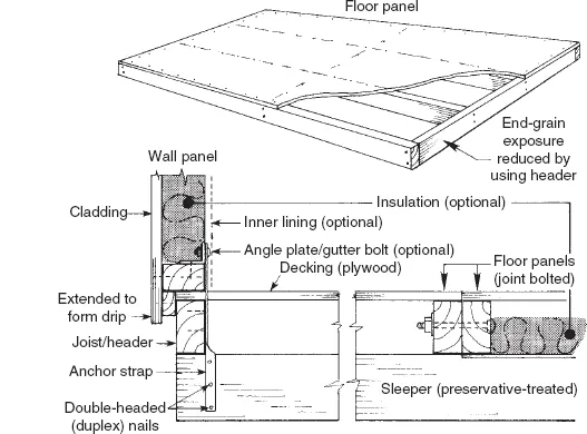
Fig. 1.2 Floor panels and wall-to-floor details
1.1.1.3 Roofs
Whole roof sections can be prefabricated as shown in Fig. 1.3a to drop on to and be anchored to wall sections via bolt-on angle plates or steel straps. Joists may be cut from the solid, laminated or, for lightness, fabricated using the box–beam method (a solid timber framework clad both sides with an exterior-grade plywood). Thermal insulation may be incorporated within roof sections (but see Volume 2, section 8.10, with regard to avoiding interstitial condensation, i.e. condensation occurring within the fabric of the building).
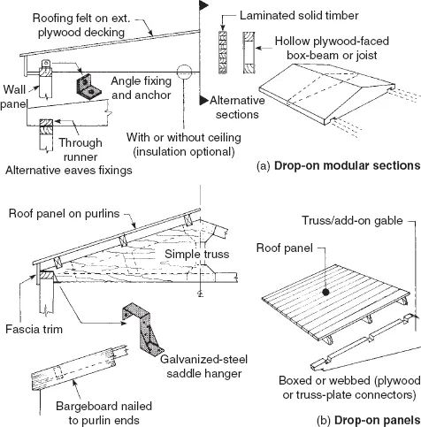
Fig. 1.3 Roof details (Note: thermal insulation not shown)
Alternatively, roof panels can be supported by simple trusses evenly spaced between add-on gable ends. As shown in Fig. 1.3b, trusses can be built up as a box section or as a timber framework with joints webbed with exterior-grade plywood or steel truss-plate connectors. Trusses can be set and anchored to wall panels, or suspended from them by anchored steel saddle-hangers.
Gable-end sections support the panel ends. Notches are cut to receive runners (purlins), their ends being covered (trimmed) with a bargeboard.
1.1.1.4 Sequence of Erection (see Fig. 1.4)
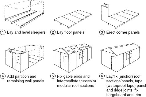
Fig. 1.4 Site hut assembly details
- Lay and level heavy-sectioned sleepers (bearers). Wood-preservative treatment is essential. (See also Volume 1, Chapter 3.)
- Lay and connect (using coach bolts) an appropriate number of floor ...
Table of contents
- Cover
- Half Title
- Title Page
- Copyright
- Contents
- Foreword
- Foreword
- Preface
- Acknowledgements
- Chapter One: Prefabricated Buildings
- Chapter Two: External Cladding
- Chapter Three: Windows
- Chapter Four: Domestic Doors, Frames and Linings
- Chapter Five: Domestic Garage Doors
- Chapter Six: Domestic Gates
- Chapter Seven: Stairs
- Chapter Eight: Wood Wall Trims and Finishes
- Chapter Nine: Casing-In and Wall Panelling
- Chapter Ten: Joinery Fitments and Purpose – Made Joinery
- Chapter Eleven: Shoring Buildings
- Chapter Twelve: Repairs and Maintenance
- Volumes and Chapters
- Index
Frequently asked questions
Yes, you can cancel anytime from the Subscription tab in your account settings on the Perlego website. Your subscription will stay active until the end of your current billing period. Learn how to cancel your subscription
No, books cannot be downloaded as external files, such as PDFs, for use outside of Perlego. However, you can download books within the Perlego app for offline reading on mobile or tablet. Learn how to download books offline
Perlego offers two plans: Essential and Complete
- Essential is ideal for learners and professionals who enjoy exploring a wide range of subjects. Access the Essential Library with 800,000+ trusted titles and best-sellers across business, personal growth, and the humanities. Includes unlimited reading time and Standard Read Aloud voice.
- Complete: Perfect for advanced learners and researchers needing full, unrestricted access. Unlock 1.4M+ books across hundreds of subjects, including academic and specialized titles. The Complete Plan also includes advanced features like Premium Read Aloud and Research Assistant.
We are an online textbook subscription service, where you can get access to an entire online library for less than the price of a single book per month. With over 1 million books across 990+ topics, we’ve got you covered! Learn about our mission
Look out for the read-aloud symbol on your next book to see if you can listen to it. The read-aloud tool reads text aloud for you, highlighting the text as it is being read. You can pause it, speed it up and slow it down. Learn more about Read Aloud
Yes! You can use the Perlego app on both iOS and Android devices to read anytime, anywhere — even offline. Perfect for commutes or when you’re on the go.
Please note we cannot support devices running on iOS 13 and Android 7 or earlier. Learn more about using the app
Please note we cannot support devices running on iOS 13 and Android 7 or earlier. Learn more about using the app
Yes, you can access Carpentry and Joinery 3 by Brian Porter,Chris Tooke in PDF and/or ePUB format, as well as other popular books in Technology & Engineering & Civil Engineering. We have over one million books available in our catalogue for you to explore.