- 160 pages
- English
- ePUB (mobile friendly)
- Available on iOS & Android
eBook - ePub
Electronic Logic Circuits
About this book
Most branches of organizing utilize digital electronic systems. This book introduces the design of such systems using basic logic elements as the components. The material is presented in a straightforward manner suitable for students of electronic engineering and computer science. The book is also of use to engineers in related disciplines who require a clear introduction to logic circuits. This third edition has been revised to encompass the most recent advances in technology as well as the latest trends in components and notation. It includes a wide coverage of application specific integrated circuits (ASCIs), many worked examples and a step-by-step logical and practical approach.
Trusted by 375,005 students
Access to over 1 million titles for a fair monthly price.
Study more efficiently using our study tools.
Information
Subtopic
Ingeniería computacional1 Two-state systems
If some condition of a manufactured article may change or be changed then the article may be classified either as a discrete-state or as a continuous-state system. The term ‘system’ simply describes the article as a whole; the article may be a component used in some large assembly or it may be a complete large assembly. The ‘state’ of the system is its condition, each different state corresponds to a different condition of the system. A system is a continuous-state system when its variable condition, its state, is able to take any value between certain limits; such systems have an infinite number of possible states. For instance the sound output from a radio receiver may be adjusted by the listener to any level from inaudible to the maximum possible output. Similarly, a car driver can select any engine speed required by use of the accelerator control. Both the radio receiver and the car engine are examples of continuous-state systems; such systems are also known as continuously-variable systems.
In contrast to the wide range of states (conditions) possible in a continuous-state system, a conventional electric light switch allows only on or off settings of the light; similarly, a car driver can use the gear lever to select one of the small number of gear ratios available. Both the lighting system with an on–off switch and the car gearbox are examples of discrete-state systems; in such systems only a finite, usually fixed, number of different states are allowed.
Many situations arise in which a designer has to choose to use either a discrete-state or a continuous-state system because it is possible to solve a particular engineering problem by using either type of system. For instance an on–off light switch may be replaced by a dimmer control which allows the user to select any light level over a wide range. Because designers frequently have to choose to use either a discrete-state or a continuous-state system they should be aware of the particular advantages and disadvantages of each type of system.
A general comparison for every possible situation cannot be made, but in a large proportion of cases the continuous-state system is more expensive to manufacture and is less reliable than a discrete-state alternative. For example the cost of a dimmer light control is typically five times that of an on–off switch. However, the dimmer control has the advantage that the user may select any level of lighting rather than just fully on or fully off. This wider range of choice given to the user is found in many, but not all, cases when a continuous-state system is chosen rather than a discrete-state system.
1.1 Two-state systems
Discrete-state systems which have only two possible states, for example a simple on–off light switch, are particularly easy to manufacture in many cases. This book is concerned only with systems which are constructed entirely from discrete-state components which are restricted to two possible states, i.e. the components are themselves two-state systems. Surprisingly, this very strict limitation placed on the components imposes only one restriction on the complete system; it must be a discrete-state system, but it may have any number of states because two-state components may be combined together so that they form a multiple-state system.
Two-state components are often called logic elements and complete systems which are constructed from such components are logic systems, logic circuits or logic networks; the reasons for these names should become apparent in Chapter 2. An on–off light switch is a two-state device as are many other types of switch; an alternative name for logic circuits is switching circuits. One further name is digital circuits.
Nearly all the systems (circuits) which will be described in this book can be constructed using any two-state device as the basic component but the use of electronic two-state components is emphasized. Systems built using electronic logic components have become familiar everyday items; before the early 1970s such systems were only used in specialized engineering applications. The application of electronic devices to a wide range of new and existing products followed the development of modern electronic logic elements which have many advantages when compared with other types of logic or switching component. They are exceedingly small, require very little power, operate quickly, and are extremely cheap. The cost of a single logic element within a system containing many elements is often less than 0·001 pence. Manufacturing techniques and component design appear to be continuing to advance rapidly; it is probable that element costs will continue to decrease, typically halving every three to five years.
An additional advantage of modern electronic components is that those used in two-state systems have exceptionally high reliability. Well-constructed systems containing several thousand million components will operate with over 109 element switchings per second for periods of several years without any component failures. If the components were not electronic (e.g. mechanical springs and levers, hydraulic devices or electromechanical relays) failures would occur so often in such large systems that they would rarely, if ever, operate successfully.
1.2 Electronic two-state systems
There are many ways to construct electronic circuits so that they are two-state circuits. The most common circuit designs are such that any circuit input or output which is above some specified voltage level is defined to be in one of the two states. When an input or output is below some much lower level it is in the other state. It is essential that there is a well-defined gap between the two voltage levels. All the logic circuits (and those connected to them) must be designed so that all the inputs and outputs can only take up the specified voltage levels; they must never be held in the region between the two levels. Figure 1.1 illustrates this method of defining the logic states, the voltage levels shown are those most commonly used at the present time. Note the difference indicated in the levels for inputs and outputs. The requirement that an output ‘1’ voltage must be higher than the value recognized as ‘1’ at an input, and that an output ‘0’ is lower than the value of an input ‘0’ ensures that when the output of one circuit is connected so that it supplies the input to another circuit the level will always be correctly recognized.
Most real circuits have construction features which restrict how much higher than the minimum 1 level, or how much lower than the maximum 0 level, input voltage levels may be without damage occurring. Although inputs are not allowed to be set to values between the two levels a change of an input from one level to the other requires that the voltage passes through the unallowed (transition) region. Components are designed to ensure that no problems occur provided that the change through the transition region is made quickly and smoothly.
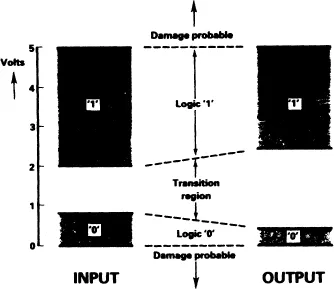
Fig. 1.1 Definitions of logic states (TTL levels)
It is convenient to give names to the two logic states so that they are easily identified. If one works entirely with such names then any logic network designed may be constructed using logic components of any single type. The nomenclature adopted in Fig. 1.1 is that the upper level (state) is called 1 (ONE) and the lower level is called 0 (ZERO). Alternative pairs of names in common use include HIGH and LOW, UP and DOWN, ON and OFF, and TRUE and FALSE. The names 1 and 0 are those which will be used in this book, although others will be used if they are particularly suited to some application.
Detailed consideration of the many ways in which electronic circuits may be designed to behave as two-state elements are to be found in books concerned with the design and analysis of electronic circuits. Any reader interested in such details should refer to one of the many books on these subjects. This book is concerned with the design and behaviour of circuits which are constructed from components, where each component is a complete two-state system which is normally – but not necessarily – an electronic circuit.
1.3 Common electronic logic components
With the exception of a few special applications, modern electronic logic networks are constructed from two-state components which are puchased in the form of integrated circuits. A logic integrated circuit is an electronic circuit consisting of components (resistors, transistors, etc.) connected so that the resulting circuit functions as the required logic device. The complete circuit is fabricated on the surface of a small piece of a single crystal of a very pure semiconductor material (the piece of crystal is often called a chip). Most devices are made with silicon as the semiconductor material and the chip is typically 1 to 10 mm square and about 0.5 mm thick. The chip is encapsulated in a protective casing of plastic or ceramic which is larger than the chip. Metal leads are fixed to the chip and extend beyond the plastic or ceramic case to allow electrical connections to be made to the circuit inputs, outputs and power supply points. This packaging arrangement enables the integrated circuit to be easily handled and connected into a larger network by hand or by automatic machines. Figure 1.2 is an outline drawing of one of the most common encapsulations for small and medium size integrated circuits; the dual in line (DIL) package.
At present the relatively simple electronic logic components required for initial studies of logic circuits are readily available in two distinctly different circuit forms; transistor-transistor logic (TTL) and complementary symmetry metal oxide semiconductor logic (CMOS). The two systems are different and components of the different systems should not be interconnected unless the complete circuit specifications are understood. However, when this is necessary, special interconnecting (interface) circuits are used to make connections between the two different systems. As adequate ranges of components are available in each of the common systems, devices from a single system can be used for most designs and the interconnection problem may be avoided.
The TTL and CMOS systems supersede several much earlier ones, for example resistor-transistor logic (RTL) and diode-transistor logic (DTL). There is such a large investment in the manufacture of TTL and CMOS components, and in equipment that uses them, that these types will probably be the ones most commonly used for some time. However, even these types are regularly modified; devices with revised (improved) specifications become available at regular intervals. For applications requiring very high speeds of operation (above 100 million operations per second) components using emitter-coupled logic (ECL) are required. Great care and a knowledge of high speed circuit layout techniques are necessary to build circuits to operate at such high speed.
When the various component types were first introduced it was possible to describe their differences easily. Early TTL components were much faster than early CMOS ones but required much more power. However, TTL devices have been developed so that modern versions use much less power than earlier forms, also modern CMOS devices now operate much more quickly than older forms. Further, there are many different families of both types available and each family has been designed to have characteristics making it suitable for certain applications. Except in Chapter 7, the various types will not be considered and no assumptions will be made concerning the type of two-state components required for circuit construction. In nearly all cases any type of component – including non-electronic ones – may be used....
Table of contents
- Cover
- Halftitle
- Title
- Copyright
- Preface
- Contents
- 1 Two-state systems
- 2 Basic elements of combinational logic
- 3 The design of combinational logic circuits
- 4 Sequential logic elements
- 5 Sequential logic systems
- 6 The design of sequential logic circuits
- 7 Electronic logic circuits
- 8 Large logic networks
- 9 Application specific integrated circuits (ASICs)
- Appendix A Number systems and base conversions
- Appendix B Maxterm representation of circuits
- Appendix C A note concerning symbols
- Appendix D Solutions to selected problems
- Bibliography
- Index
Frequently asked questions
Yes, you can cancel anytime from the Subscription tab in your account settings on the Perlego website. Your subscription will stay active until the end of your current billing period. Learn how to cancel your subscription
No, books cannot be downloaded as external files, such as PDFs, for use outside of Perlego. However, you can download books within the Perlego app for offline reading on mobile or tablet. Learn how to download books offline
Perlego offers two plans: Essential and Complete
- Essential is ideal for learners and professionals who enjoy exploring a wide range of subjects. Access the Essential Library with 800,000+ trusted titles and best-sellers across business, personal growth, and the humanities. Includes unlimited reading time and Standard Read Aloud voice.
- Complete: Perfect for advanced learners and researchers needing full, unrestricted access. Unlock 1.4M+ books across hundreds of subjects, including academic and specialized titles. The Complete Plan also includes advanced features like Premium Read Aloud and Research Assistant.
We are an online textbook subscription service, where you can get access to an entire online library for less than the price of a single book per month. With over 1 million books across 990+ topics, we’ve got you covered! Learn about our mission
Look out for the read-aloud symbol on your next book to see if you can listen to it. The read-aloud tool reads text aloud for you, highlighting the text as it is being read. You can pause it, speed it up and slow it down. Learn more about Read Aloud
Yes! You can use the Perlego app on both iOS and Android devices to read anytime, anywhere — even offline. Perfect for commutes or when you’re on the go.
Please note we cannot support devices running on iOS 13 and Android 7 or earlier. Learn more about using the app
Please note we cannot support devices running on iOS 13 and Android 7 or earlier. Learn more about using the app
Yes, you can access Electronic Logic Circuits by J. Gibson in PDF and/or ePUB format, as well as other popular books in Tecnología e ingeniería & Ingeniería computacional. We have over one million books available in our catalogue for you to explore.