Centrifugal pumps are used in the majority of all fluid flow processes. The complexities of the fluid flow patterns and design practicalities for these pumps have involved intensive engineering endeavors for well over 100 years. The requirements of these pumps vary considerably for different industries and applications. Power plant requirements for centrifugal pumps are among the most demanding of any industry. With the advent of modern computational fluid mechanics (CFM), finite element analyses (FEA), measurement sensors, and digital data processing, the evolution of centrifugal pump technology development still continues to advance.
1.1Flow Complexity and Flow-Path Geometry
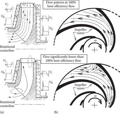
The flows in both stationary and rotating internal flow passages of centrifugal pumps are quite complicated. Even when operating at the best efficiency point (BEP) 100% design flow, centrifugal pump internal flow fields are somewhat unsteady. At off-design operating flows the internal flows are highly unsteady. Showing still pictures like Figure 1.1 does not convey this flow unsteadiness, providing only instantaneous snap shots of typical flow fields within and around the rotating impeller flow passages.
Figure 1.1Centrifugal pump impeller snapshots of flow patterns. (a) Radial flow views and (b) circumferential flow views relative to rotating impeller.
Centrifugal pumps are closely related to hydro turbines, the fundamental distinction being that in turbines mechanical energy is extracted from the fluid, whereas in pumps mechanical energy is transferred to the fluid. This distinction results in a major fluid dynamical difference between centrifugal pumps and hydro turbines, namely that within turbine impellers the fluid is accelerated like in a nozzle, while within pump impellers the fluid is decelerated like in a diffuser. This fundamental difference makes highly efficient hydraulic design considerably more challenging for centrifugal pumps than for turbines. An insightful way to understand this fundamental difference is to view the pump impeller as an assembly of rotating diffuser channels and to view the turbine impeller as an assembly of rotating nozzles. Figure 1.2 shows a clear visual distinction between centrifugal pump and hydro turbine impellers. One immediately notices that a pump impeller typically has about one-third as many vanes as a turbine impeller. One also immediately notices that a pump impeller vane correspondingly wraps around the impeller about three times the wrap angle of a turbine vane.
Figure 1.2Comparison between Francis impellers for (a) a pump and (b) a turbine.
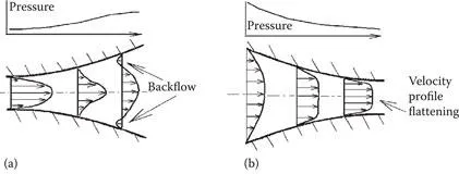
Figure 1.3 illustrates the fundamental fluid dynamics difference between a diffuser and a nozzle. In the direction of flow a nozzle’s flow area decreases and thus average fluid velocity increases, and in consequence it yields static pressure decreasing and velocity profile flattening in the direction of flow. In contrast, a diffuser’s flow area increases and thus average fluid velocity decreases in the direction of flow, and in consequence it yields static pressure increasing and velocity profile arching in the direction of flow. When the degree of flow deceleration in a diffuser exceeds some critical level, the adverse pressure gradient combined with velocity profile arching initiates backflow (called flow separation) at the flow channel boundary. Flow separation is a churning action that significantly wastes flow energy through viscous dissipation into heat. Clearly, flow separation is not consistent with high-efficiency hydraulic performance. An efficient diffuser must be long enough so that its flow area increase rate is sufficiently gentle to avoid flow separation. In contrast, an efficient nozzle can be relatively short since flow separation is not a concern, given a nozzle’s inherent favorable pressure gradient and velocity profile flattening. Understanding this basic contrast between a diffuser and a nozzle leads one to a basic insight into why highly efficient hydraulic design is more challenging for centrifugal pumps than for turbines.
Figure 1.3Velocity profiles and pressures for (a) diffusers and (b) nozzles.
As typified in Figure 1.2, the contrasting differences between pump impeller geometry and turbine impeller geometry clearly reflect this fundamental difference between diffusers and nozzles. That is, the relatively long wrapped-around pump impeller vanes form a considerably more gentle flow area transition than the relatively shorter turbine vanes. Optimum turbine impeller geometry benefits from shorter vanes by allowing many more vanes for better flow guidance without excessive eye exit flow blockage.
Realizing the basic differences between nozzles and diffusers, one can also appreciate the ...