- 184 pages
- English
- ePUB (mobile friendly)
- Available on iOS & Android
eBook - ePub
Electron Diffraction in the Transmission Electron Microscope
About this book
This book is a practical guide to electron diffraction in the transmission electron microscope (TEM). Case studies and examples are used to provide an invaluable introduction to the subject for those new to the technique. The book explains the basic methods used to obtain diffraction patterns with the TEM. The numerous illustrations aid the understanding of the conclusions reached.
Trusted by 375,005 students
Access to over 1.5 million titles for a fair monthly price.
Study more efficiently using our study tools.
Information
Subtopic
Biochemistry1 Diffraction and the electron microscope
When we look at a distant street light through a finely woven net curtain or an umbrella we see a pattern of bright spots. This pattern is not an image, it is a diffraction pattern. We see a regular array of spots because the fabric of the curtain or the umbrella also has a regular, periodic weave. The pattern that we see is telling us about the periodicity of the weave and its orientation; if you rotate the fabric about a direction perpendicular to its surface, the pattern of spots will also rotate. We will look at this phenomenon in more detail at the end of the next section.
1.1 How a lens forms a diffraction pattern
We are most familiar with the use of lenses to form a (usually) magnified image of an object; for instance, with a magnifying glass or an optical microscope. However, any converging lens used in this way is also forming a diffraction pattern. What happens can be understood by reference to Figure 1.1. Here we have a periodic object (it could be a piece of net curtaining) placed in front of a converging lens which is illuminated by a parallel beam of monochromatic (single wavelength) light. Some of the light is transmitted undeviated through the object and some is ‘scattered’ (some will also be absorbed). The undeviated light travels parallel to the optic axis of the lens and is focused by the lens so that it passes through the principal focal point F0 at a distance from the lens equal to the focal length, f. A plane drawn through F0 perpendicular to the axis is the back focal-plane of the lens (note that there is a conjugate, i.e. optically equivalent, front focal-plane at a distance f from the lens on the object side of the lens). Light scattered at angles ± α by the object will form parallel beams which are focused to points F1 and F1’ in the back focal-plane, at a distance from the axis proportional to the angle α. This pattern of spots formed when the transmitted and scattered beams are focused into the back focal-plane is the diffraction pattern. In fact, for an infinite, periodic object such as our net curtain the spots are only formed for rays that are scattered in specific directions (we will learn the rule that governs these directions later). The rays that form the diffraction spots in the back focal-plane go on to form an inverted image in the image plane. If you follow the three rays shown in Figure 1.1 that are emerging from any of the three apertures O1, O2 or O3 of the object, you will find that they end up at the same point in the image (rays from O1 end up at I1 for example, as you would expect), each having passed through a different diffraction spot. In other words, information about the object is contained in each diffraction spot. A direct consequence of this effect is that, in order for the lens to form an image of the object (i.e. in order to resolve the weave of the curtain material), at least two diffracted beams should enter the objective lens and be allowed to recombine in the image plane. This principle was first described by Ernst Abbe in the 19th century and is known as the Abbe criterion.

If we explore a little further, we find that there is a definite relationship between the periodicity and orientation of the object and the spacing and orientation of the spots in a diffraction pattern. You can easily see what this relationship is if you hold a set of meshes, net-curtain materials or diffraction gratings of varying periodicity in front of a laser pointer (do NOT look directly into the laser beam) or other small torch and view the diffraction pattern produced on the wall on the opposite side of the room. You will find that the spacing of the diffraction spots is inversely proportional to the object’s periodicity (for instance, if you halve the spacing of the grating or mesh, the spacing of the diffraction spots doubles) and that the separation of the spots produced by the grating or by the weave of the net is perpendicular to the lines of the grating (Figure 1.2). (If you do not have a set of such objects, you can see the size effect by rotating a mesh about the direction of one of the threads, thus effectively shortening the mesh periodicity perpendicular to the direction of rotation. The spacing of the corresponding diffraction spots will increase). What we have been looking at in the diffraction pattern is also known as the reciprocal lattice because of the inverse (reciprocal) relationship it bears to the direct lattice — the object.

1.2 Introduction to diffraction in the TEM
A transmission electron microscope (TEM) consists of a source of electrons (the electron gun) and a series of electromagnetic lenses, as shown in Figure 1.3 (see also Table 1.1). The most critical components of a magnetic lens are the soft-iron pole-pieces which produce an axially symmetric magnetic field for focusing the electrons. The rest of the lens is a magnetic yoke containing the windings for energizing the lens with a d.c. current. By varying this current, the magnetic field, and hence the focal length of the lens, is changed. This ability to change the focal length is one of the most important ways in which magnetic lenses differ from glass ones. Another difference is that, unlike the glass lenses in a light microscope, magnetic lenses in an electron microscope, because of their construction, size and weight, cannot be moved physically with respect to one another in order to focus the image, although the specimen can be moved up or down in the holder to achieve a certain amount of focusing. We will see some other differences between the two types of microscope later.
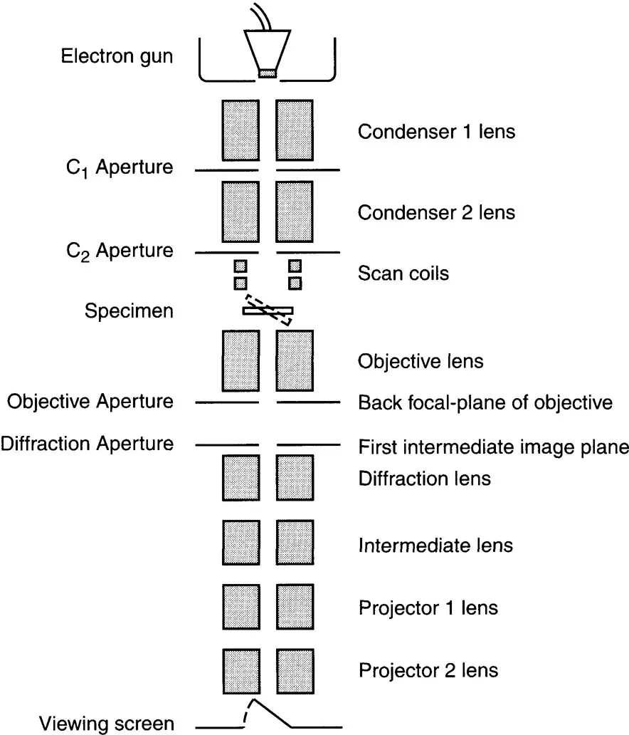
Table 1.1. Nomenclature used by different manufacturers for the imaging lenses in a TEM
| FEI/Philips | JEOL | Hitachi |
| Objective | Objective | Objective |
| Diffraction | First intermediate | First intermediate |
| Intermediate | Second intermediate | Second intermediate |
| Projector 1 | Third intermediate | First projector |
| Projector 2 | Projector | Second projector |
The specimen is placed in a holder in the front focal-plane of the objective lens (Figure 1.3), i.e. at a distance f in front of the lens. Figure 1.4 shows schematically the ray paths for the imaging system of a TEM that employs three stages of magnification. The magnified image produced by the objective in its image plane serves as an object for t...
Table of contents
- Cover
- Half Title
- Title Page
- Copyright Page
- Table of Contents
- Abbreviations
- List of symbols
- Preface
- 1. Diffraction and the electron microscope
- 2. The reciprocal lattice and Bragg’s Law
- 3. The reflecting sphere
- 4. Finding your way around reciprocal space: Kikuchi diffraction
- 5. The intensities of reflections
- 6. Determination of the Bravais lattice, point group and space group
- 7. The fine structure in electron diffraction patterns
- Appendix A: Some basic crystallography
- Appendix B: An introduction to space groups
- Appendix C: Some useful crystallographic relationships
- Appendix D: Relativistic electron wavelengths
- Appendix E: Mathematical definition of the reciprocal lattice
- Appendix F: Computer programs concerning electron diffraction
- Appendix G: Answers to exercises
- Appendix H: References
- Index
Frequently asked questions
Yes, you can cancel anytime from the Subscription tab in your account settings on the Perlego website. Your subscription will stay active until the end of your current billing period. Learn how to cancel your subscription
No, books cannot be downloaded as external files, such as PDFs, for use outside of Perlego. However, you can download books within the Perlego app for offline reading on mobile or tablet. Learn how to download books offline
We are an online textbook subscription service, where you can get access to an entire online library for less than the price of a single book per month. With over 1.5 million books across 990+ topics, we’ve got you covered! Learn about our mission
Look out for the read-aloud symbol on your next book to see if you can listen to it. The read-aloud tool reads text aloud for you, highlighting the text as it is being read. You can pause it, speed it up and slow it down. Learn more about Read Aloud
Yes! You can use the Perlego app on both iOS and Android devices to read anytime, anywhere — even offline. Perfect for commutes or when you’re on the go.
Please note we cannot support devices running on iOS 13 and Android 7 or earlier. Learn more about using the app
Please note we cannot support devices running on iOS 13 and Android 7 or earlier. Learn more about using the app
Yes, you can access Electron Diffraction in the Transmission Electron Microscope by P.E. Champness in PDF and/or ePUB format, as well as other popular books in Technology & Engineering & Biochemistry. We have over 1.5 million books available in our catalogue for you to explore.