- 320 pages
- English
- ePUB (mobile friendly)
- Available on iOS & Android
eBook - ePub
Engineering Documentation for CAD/CAM Applications
About this book
This book emphasizes the importance of consistent, well-planned, and computer-oriented engineering documentation systems to engineering, manufacturing, and accounting. It discusses the systems needed to optimize flow of information and increase the efficiency of modern CAD/CAM systems.
Trusted by 375,005 students
Access to over 1.5 million titles for a fair monthly price.
Study more efficiently using our study tools.
Information
INTRODUCTION
1
A friendly revolution has begun in engineering departments of almost all manufacturing companies. Over the years, design methods have gradually been changing. More sophisticated methods of determining optimum designs have been invented, and competition, both foreign and domestic, has made it inevitable that the engineer accept and utilize them. The computer has become a useful and well-understood tool in this endeavor.
Today, for example, it is quite usual to design gear sets by a gear analysis program. No longer does an engineer guess at a safety factor in some structural design, but, rather, uses a program such as NASTRAN or Stardyne to examine the displacements and forces on the product using finite element analysis and plotters to draw the stress analysis results. Guesswork and "cut-and-try" attitudes are eliminated.
In the 1960s, computers such as the IBM 704 as well as other smaller computers were fully appreciated and utilized by engineers, particularly in the aerospace industry. Many companies, however, felt there was no significant economic advantage to using computers to perform design calculations. Eventually, however, remote terminals, used for very limited applications, were installed even in these "holdouts."
The result of this slow but steady inroad of computers for design applications did not, unfortunately, cause the engineer to see and understand the significance of such calculations as a means to transmit the resulting data "electromagically" to other departments of a company. Consequently, the results of most design calculations were arduously recopied onto appropriate drawings or bills of material.
The "paper work" of the engineering department languished. Often a designer or drafter, too slow or less competent, was transferred to the engineering standards department. The standards thus generated did not portray the future requirements, but merely documented the past. Seldom was an attempt made to determine whether practices, present or past, were beneficial and economical to other departments. Not infrequently a contest emerged between engineering and manufacturing. Manufacturing personnel stated, "I can make anything they can design." Engineers took up the challenge raised by manufacturing, creating ever more exotic designs which were not always necessary. Thus the battle was joined.
Another phenomena also had its effect. Many companies used to place their engineers into training programs which allowed them to work in, and become acquainted with, various manufacturing disciplines. It was not unusual to see graduate engineers working on an assembly line as a part of this training. As engineers became scarce, and as union rules or manufacturing practices discouraged this direct participation, the engineers slowly lost touch and became unaware of the manufacturing techniques, their availability, and their limitations. To this day, many engineers design products, parts, and assemblies, without the slightest idea of how, when, or where they will be manufactured. In addition, the long lead time between the finished drawing release and the first part made is not conducive to feedback in assisting the engineer to understand the errors may have been made. Lack of this feedback loop has helped to perpetuate errors, more costly designs, and a lack of awareness by engineers of the problems they may have contributed to the manufacture, product cost, and increased lead-time requirements.
Engineers are rarely given cost data. Some chief engineers feel such knowledge might destroy the designers creativity. Rarely does any design analysis program utilize cost as a variable. Consequently another type of feedback to the engineer is missing. Value engineering has been useful, but is sporadic.
In much the same manner, the influence of data processing and data base requirements of a manufacturing firm have not been emphasized to engineers and designers. If hundreds of people in manufacturing must write 43-digit part numbers every day for a host of parts, the engineer may be blithely unaware of the consequences in time, accuracy, and confusion. If the engineer prepares a handwritten bill of material on a drawing, and someone else retypes it into a form for a computer system, the potential errors do not seem to affect him or her.
Aerospace and computer manufacturers learned early the penalties of poor data generation. The complexity of the product simply did not allow for many errors to occur. Giant steps were taken by such companies to clean up their data so it could be processed in a streamlined manner. Unfortunately any progress on their part could be easily sneered at by other chief engineers. After all, "the government" was paying for this fancy kind of documentation. The realization that economics of scale and faster flow of data were achieved seemed to go over their head.
In addition to aerospace and computer manufacturers, manufacturers in the automotive and tractor areas adopted sound engineering practices and good documentation control, short part numbers, and some retrieval systems. While these documentation techniques were well planned, they were essentially manual. Conversion of these methods to a more mechanized process came only after a long and agonizing period of adjustment.
Today, two basic types of documentation systems appear to predominate in the engineering field. The first could be described as a job order system. In this system the engineering documentation methods are almost completely ignored by manufacturing and accounting. The part number becomes secondary to an accounting job number which is tied to a specific customer order. Engineering changes are meticulously documented according to the customer affected. Interchangeability is carelessly applied. The motto "we never make the same thing twice" is gleefully and proudly proclaimed.
Personnel of a company manufacturing rock crushers stated, "no two rock crushers are identical." The discovery that 90% of all the parts in every rock crusher were identical did not cause the slightest change in the job number system, which required that each part of each crusher be manufactured under a separate job number, completely ignoring any advantages of mass production. The lack of awareness on the part of both engineers and accountants in this type of system has contributed to unnecessarily high cost products, and, in several cases, eventual bankruptcy.
The second type of system could be described as a part number system, and presumes a part or a product can and will be used again. Thus, the part number documentation is used not only in engineering, but also in manufacturing and accounting. Many companies are moving to develop systems such as this; few, if any, are converting to a job number system.
No matter which of these systems has been in existence within a company, both types of companies have resisted mechanization. Let's examine some possible reasons why this resistance persists.
We have already described how the computer has been used in design but the results have been manually transferred to other media such as an engineering drawing. Perhaps the simplest answer to the resistance to mechanization can be found in the attitudes, the education, and the objectives of the engineer and designer. Engineers design "things." These "things" do not portray "flow." The design is an entity, not a portion of a stream. The result of a design is a picture, not a piece of paper. The change in a design is a new picture, not an engineering change notice. The parts composing the design are additional drawings, not physical parts made with corresponding tools, work centers, and inventories.
Engineers do not receive data, they create it. Therefore, they have never felt the urgency of receiving late, incomplete, or inaccurate data. They have been shielded from the consequences of their actions. One example might illustrate this condition.
A manager of production in a company which manufactures tractors noted that a hole cover was designed to be chained to the body of the product; the chain was fastened to the cover by means of a hole through a block, which was, in turn, welded to the cover. The block had been welded off-center to the cover. If the block could be moved to the center of the cover the cover could be machined more rapidly and economically using the block in the chuck of the machine. The present design required holding the cover in "soft jaws" to machine it. A call to engineering was met with the comment, "You don't understand what we are doing, just build the parts as we have designed them." For 30 years the production manager watched while six covers per product were manufactured expensively.
The engineer must become a part of the engineering-manufacturing process. Competition, economics, the very existence of a company mandates this. Isolation must cease. It is time to examine the means by which engineers and designers communicate to the rest of the world.
At times data processing personnel have made some tentative attempts to try to rectify engineering systems. They were outnumbered. Unfortunately, too, data processing personnel are usually more accounting than engineering oriented. Thus it was difficult for them to have empathy for the problems in engineering and to find the means to solve them. Only engineers can completely solve engineering problems. We must elicit their interest and cooperation.
If nothing else has been able to induce engineering systems to change, computer-assisted drawing/computer-assisted manufacturing (CAD/CAM) will. Perhaps at first CAD/CAM systems will be installed to perform drafting. If this occurs it will be unfortunate, since the full power of an integrated CAD/CAM system will not then be utilized. Soon, however, some uneasiness is bound to appear when either drafting productivity does not meet expectations, or the speed with which drawings are prepared is lost when other data is transmitted in the old and slow manner. CAD/CAM may well be the major reason why engineering systems must be changed and the reason they will be changed. Let us then look at the outline of a flow of data as it may happen when an integrated CAD/CAM system is utilized. We will then point out those sections in this book which we will discuss that will assist in streamlining the documentation flow.
Figure 1 illustrates data flow through engineering as marketing and engineering cooperate to prepare a new product or utilize an old one. The chart implies a cathode ray tube (CRT) on-line to a data base which contains all current product specifications and the corresponding bills of material. Entering this data base with customer specifications allows the engineer to obtain a family of products which have been previously designed to meet the general requirements of the customer. Examining the available products and comparing them to the customer specifications may determine a match on some or all of the modules of an existing product. If such is the case, the proper bills of material can be immediately identified and issued. We will discuss how this type of data can be planned in the section on "Modular Design (Chap. 9).
Should no existing product meet the requirements, a "family" bill of material and set of specifications can be displayed. A new design can be initiated utilizing preplanned design specifications, design analysis programs, and a family bill of material. We will discuss how this data might be prepared in Chapter 5 on design retrieval and family drawings for CAD/CAM.
As the general bill of material is further detailed, use of the family of parts implied by the bill of material can be used to prepare a cost estimate. In addition, a skeleton bill of material can be prepared and, with the family lead times, used to develop a "Christmas tree," or exploded bill of material which can be used to graphically portray when each new design must be completed. Any parts which can be utilized from old designs can be "released" into the normal stream so that planning for their acquisition may be done immediately through the material requirements planning system (MRP). We will discuss the procedures necessary to achieve this in Chapter 7. Finally a customer proposal can be prepared with system drawings, delivery dates, and costs.
To make this possible isn't it important to make sure the engineering systems become part of the company flow and that they are streamlined?
Figure 2 shows a similar flow chart through a CAD/CAM system at the piece part and assembly level.
When a design requirement is known, the part or assembly is searched for through a design retrieval system. A family drawing and a corresponding catalog with critical dimensions are displayed. Should the dimensions for a previously designed part appear to be correct, the actual piece part drawing is displayed for confirmation. If it is adequate, it may be released immediately. If not, the family drawing is then recalled and the alphabetical dimensions replaced with the actual dimensions. If necessary, design analysis techniques can be used to optimize the design, and producibility tips from industrial engineering applied to minimize the cost of the new parts. The family drawing and the finished drawing are prepared using customized design and drafting standards. We will discuss the economic advantages of piece part drawings later.
Once the design is complete, the "text" data can be "stripped" from the design and transmitted to the data processing business systems requiring such data.

Figure 1 Integration of CAD/CAM systems in marketing and engineering require that engineering documentation have integrity and an orderly flow.
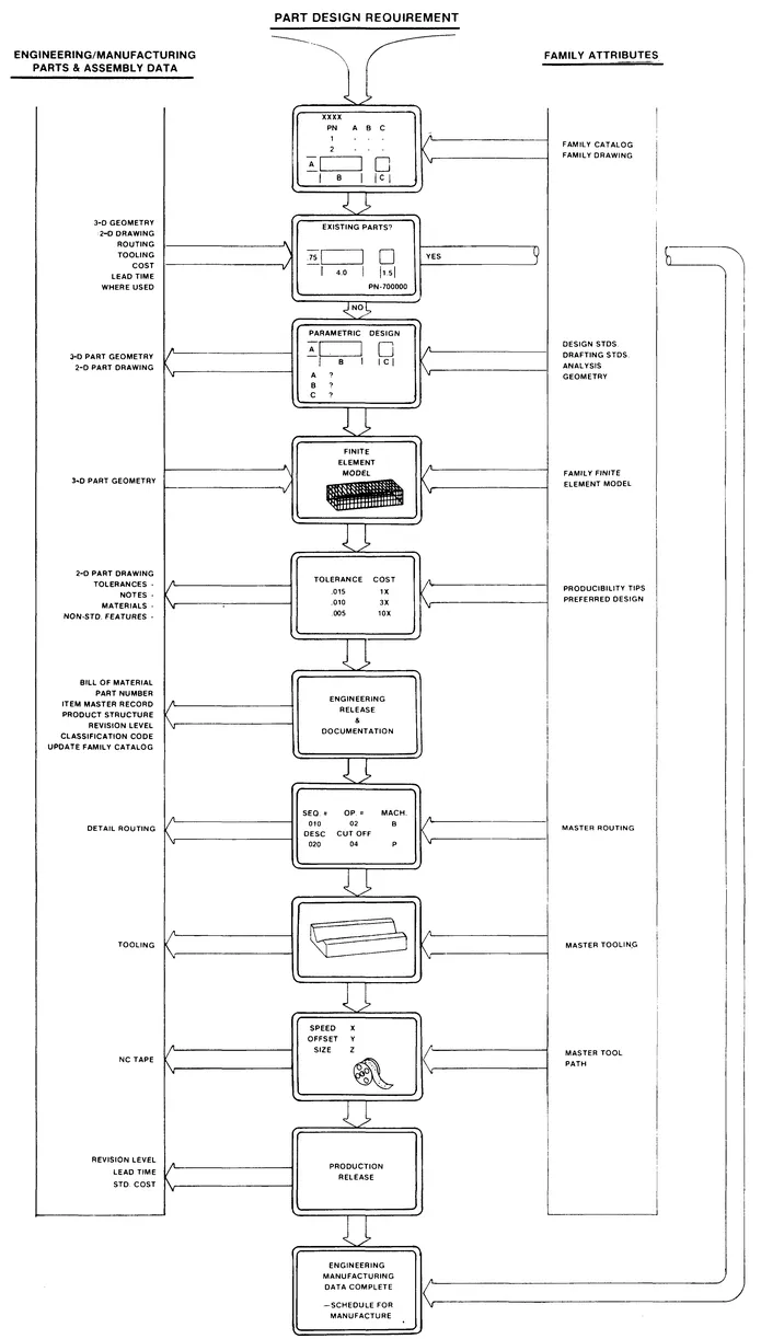
Figure 2 Detailed design requires an accurate data base, a retrieval system, and accurate engineering data.
This data is also discussed in Chapter 7. The need for proper structuring of the data is discussed in Chapter 8. Finally, engineering may use the geometry of the new part to prepare a specific routing based on a family master routing, in addition, tooling and numerically controlled (NC) machine tool cutter center line data can be prepared from the original geometry and surfaces prepared by the designer.
If we are to take advantage of this powerful tool, the ingredients must work together not in opposition. We hope the following chapters will go far to clarify the reasons for change and introduce the means for so doing.
A WORD ABOUT DATA PROCESSING
2
For many reasons, engineers and designers have looked on data processing as an unnecessary evil. "Let someone else do it" has been the motto. Consequently, clerks have been enlisted to take basic design data retranslate it into the information required for business systems. Without participating in the design of such systems, the engineer does not recognize the faults or inconveniences of the old engineering systems which are being used. Perhaps some brief analogies and a comparison of past communication devices will serve to illustrate and emphasize...
Table of contents
- Cover
- Half Title
- Series Page
- Title Page
- Copyright Page
- Dedication
- Preface
- Contents
- 1 Introduction
- 2 A Word About Data Processing
- 3 Part Number Systems
- 4 Piece Part Drawings
- 5 Design Retrieval
- 6 Family Drawings for CAD/CAM
- 7 General Concepts of a Product Identity System
- 8 Product Structuring
- 9 Modular Design
- 10 Job Shop Versus Mass Production
- 11 The Engineering Manufacturing Process
- 12 A Final Look at Mechanized Systems
- Index
Frequently asked questions
Yes, you can cancel anytime from the Subscription tab in your account settings on the Perlego website. Your subscription will stay active until the end of your current billing period. Learn how to cancel your subscription
No, books cannot be downloaded as external files, such as PDFs, for use outside of Perlego. However, you can download books within the Perlego app for offline reading on mobile or tablet. Learn how to download books offline
Perlego offers two plans: Essential and Complete
- Essential is ideal for learners and professionals who enjoy exploring a wide range of subjects. Access the Essential Library with 800,000+ trusted titles and best-sellers across business, personal growth, and the humanities. Includes unlimited reading time and Standard Read Aloud voice.
- Complete: Perfect for advanced learners and researchers needing full, unrestricted access. Unlock 1.5M+ books across hundreds of subjects, including academic and specialized titles. The Complete Plan also includes advanced features like Premium Read Aloud and Research Assistant.
We are an online textbook subscription service, where you can get access to an entire online library for less than the price of a single book per month. With over 1.5 million books across 990+ topics, we’ve got you covered! Learn about our mission
Look out for the read-aloud symbol on your next book to see if you can listen to it. The read-aloud tool reads text aloud for you, highlighting the text as it is being read. You can pause it, speed it up and slow it down. Learn more about Read Aloud
Yes! You can use the Perlego app on both iOS and Android devices to read anytime, anywhere — even offline. Perfect for commutes or when you’re on the go.
Please note we cannot support devices running on iOS 13 and Android 7 or earlier. Learn more about using the app
Please note we cannot support devices running on iOS 13 and Android 7 or earlier. Learn more about using the app
Yes, you can access Engineering Documentation for CAD/CAM Applications by Charles S. Knox in PDF and/or ePUB format, as well as other popular books in Technology & Engineering & CAD-CAM. We have over 1.5 million books available in our catalogue for you to explore.