Work with (gates) the building blocks of computers
Discover logic circuits that can make decisions
See how computers work with ones and zeros
Understand how computers count and keep track of numbers
Build and test memory circuits
Implement hardware using code
Have fun while learning about the Arduino
Description As computer technology has evolved, there have been two groups of people: the hardware group that understands the machine, and the software group that codes in high-level programming languages. This book puts the two together by providing an understanding of the nuts and bolts of digital devices and implementing hardware operations by coding a microcontroller. We use the Arduino microcontroller, which is embraced by the world-wide maker community of well over 300, 000 people of all ages and technical backgrounds. The projects start at ground level and scaffold upward to fun challenges. We begin with a background on digital circuitry and cover the operation of the Arduino microcontroller. From there, we examine digital logic gates, which are the building blocks of computer hardware, and see how they make decisions. Next, we explore how digital devices work with numbers and do arithmetic along with how they count binary numbers. We also see how data moves between points in serial or parallel form as we build and test the circuitry to do the work. The topic of random number generation is explained, and we design a few simple computer games to see how this all works and have some fun. The book leads up to the reader producing a final capstone project. The format of the book is perfect for a digital electronics high school or college course, but easy enough to follow so that anyone with a basic background in DC circuits will have an enjoyable time with the many projects. What will you learn You will learn that there is nothing mysterious about the digital devices that make up a computer, or the code that programs a computer to function. We cover the basic hardware as it is constructed into functional sections of a modern computer. You will learn about gates, flip-flops, registers, counters, and data I/O. Who this book is for Anyone with a background in electricity and electronics with the knowledge of constructing circuits on a breadboard should have no problem using this book. It is designed for people with inquisitive minds in the hope that both the hardware projects and code samples are modified by the reader to gain additional information. Table of Contents 1. A Bit about Arduino 2. Digital Function Implementation 3. Designing Functional Computer Circuits 4. Memory Devices 5. Registers and Numbers 6. Counters 7. Multiplexing and demultiplexing 8. Addresses, specialized counters, and serial monitor interaction. 9. Random Numbers 10. Interactive I/O 11. Capstone project About the Authors Bob Dukish has spent nearly 40 years working and teaching in the field of technology. After serving in the military, working as a components engineer, and running a corporation, Bob now teaches digital design classes at Kent State University. He has Associate Degrees in Avionic Systems, and in Electronic Engineering Technology, a Bachelor's Degree in Physics from Syracuse University, and Master's Degrees from Rensselaer Polytechnic Institute and Kent State University, and he is a lifelong learner.
Trusted by 375,005 students
Access to over 1.5 million titles for a fair monthly price.
We will explore one of the most popular microcontrollers used in the maker movement and now also widely used in many college-level courses in digital electronics, computer architecture, and programming. Many books are available on specific aspects of computer hardware and software. With the help of the Arduino, we will attempt to tie together what at first glance may seem to be very diverse technical subjects. With a firm understanding of the most basic fundamental concepts of electronics and computer technology, only your imagination will be the limit as to where you apply the knowledge.
Structure
Why are computers digital?
What can I do with a microcontroller?
How does the Arduino work?
How to write a program to replace hardware?
Objective
You should be able to identify digital signals and logic levels, differentiate between popular Arduino boards and describe the available resources, and you will work within the Integrated Development Environment (IDE) to develop a programmed solution to replace hardware circuits.
A brief background on microcontrollers
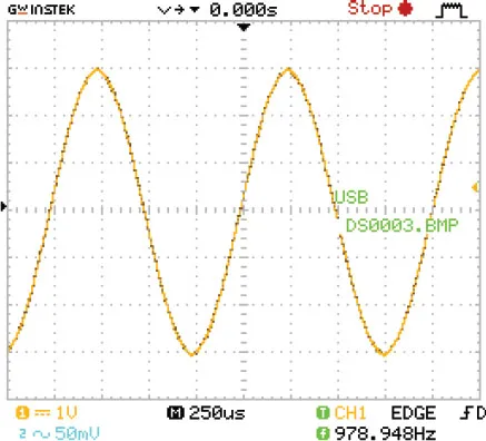
The difference between digital and analogue signals is that digital functions are easy to deal with because they have only one, of two values at any given time, whereas analogue signals can present us with an infinite range of possibilities. Figure 1.1 and Figure 1.2 show analogue and digital signals where the voltage is displayed on the y-axis with reference to time along the x-axis. We use the binary system not just because the digital concept of something being either on, or off, is easy to understand, but also because it is easy to design and build digital circuits. The ever-present light switch is a perfect example of a simple digital circuit that is either on, or off. (There is a slight in-between that we ignore because the undetermined mode is very brief and called rise and fall time.) In digital circuits, there are two states: off called low (0), or on called high (1). Computer circuits are made to operate in this manner because the circuitry is simple, the individual switches can be manufactured to be extremely small, and the device can run very rapidly. A light dimmer, on the other hand, is a prime example of an analogue circuit. We would indeed find it difficult to quickly quantify the exact value of a dim lamp’s intensity; also, the physical size of the dimming device could be quite large because of the need to dissipate heat.
The signal in Figure 1.1 is a screenshot taken of an analogue signal. It is a single audio tone of approximately 1 kilohertz, with a peak-to-peak amplitude of 6-volts:
Figure 1.1: An analogue signal
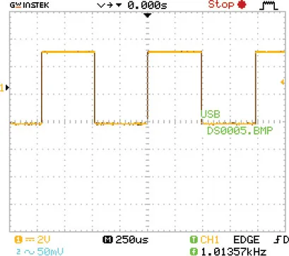
Next, we look at standard TTL digital signals where the ideal low-level bottom is 0-volts, and the ideal high is at 5-volts. We can also quantify digital pulses by both their frequency and pulse width. Figure 1.2 is a screenshot of a digital square wave with a frequency of 1 kilohertz and a pulse-width measured as having a time duration of 500 microseconds (0.000,5 seconds, or 0.5 milliseconds). That seems correct because the frequency in our figure agrees. A cycle of a square wave is the time of the high/low repetition. So, if it is square and the high pulse time is 0.5 milliseconds, and the low pulse time is also 0.5 milliseconds, then the entire event repeats at 1 millisecond. Taking a calculator and inverting the number 0.001, we see that it’s 1000, which agrees with our reading of 1 kilohertz. The nice thing about the newer Oscilloscopes where our pictures came from is that they do all the work with direct value readouts:
Figure 1.2: A digital signal
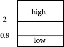
Just as in digital electronics, the signals in a microcontroller are in logic level bits considered as either a one or zero. The actual voltages have a range of values. As described graphically in Figure 1.3, the majority of Arduino boards use the standard TTL logic levels where signals from 0.8 volts down to zero are considered to be low (zero), and levels above 2 volts and up to 5-volts, are considered to be high (one):
Figure 1.3: TTL logic levels
Only dealing with zeros and ones is called the base 2, or binary system, and leads us to use Boolean mathematics when dealing with the intricacies of digital electronics, computers, and microcontrollers. The binary system concepts were developed by mathematician George Boole, who was born in the early 1800s. He was studying philosophy, as well as the logic and mathematics of ones and zeros long before the introduction of the first IBM personal computer in 1981. Many people consider counting boards and the abacus as the first computing devices developed in ancient times over 5000 years ago. The first mechanical computing machines that could solve arithmetic problems are said to have come into existence as early as the 1600s. I vaguely remember using a portable mechanical computing device in school called a slide-rule. (That was a long-winded joke that only people who came of age in the late 1960s will understand.) Before recent history, the computing machines mentioned were analogue. The universe is analogue, and this self-imposed binary limitation may seem odd to us, so it is worth having a solid understanding of the differences. It is only since the advent of vacuum tubes, relays, and transistors in the twentieth century that we needed to be concerned with George Boole’s math and the binary system of ones and zeros. The history of computing is a fascinating material, but we will leave it as the subject for another book, but I encourage you to look into it. As we now move into the era of quantum computing, the rules will change again, and knowing about the past helps one design for the future.
Introduction to Arduino
A microcontroller is a miniature computer meant for controlling peripheral devices. The utility of a microcontroller is that it is usually an embedded device within a system with the mission of examining inputs and providing corresponding outputs. Arduino is an open-source project that began in Italy in 2005 intending to make microcontroller hardware and software easy for students and tech enthusiasts to understand and use. One of the reasons the Arduino project became so popular is that boards and software are open-source. The Arduino community is quite large, and many people share ideas and projects through blogs, forums, and websites.
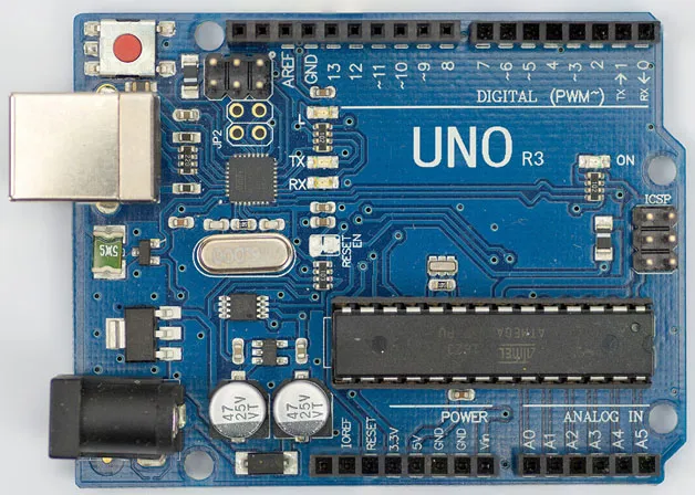
The specifications of the Arduino pale in comparison to those of a small computer such as the Raspberry Pi. For example, the Pi has a million times more RAM and a fast 32-bit processor, but it also has the great disadvantage of the need for an operating system and overhead. The Arduino is programmed using an external computer, and when it is running on its own, it provides a laser-like focus on a small task. There is also the benefit of very efficient C++ based coding where the programmer has the ability of direct manipulation of data and even direct control of the processor’s registers. Due to its efficiency, the Arduino specifications are adequate, and it is very good at its job as a controller. A company named Atmel produces the main Integrated Circuits (ICs) used in the most common Arduino boards. The IC part number for the boards we will be using is ATmega328P. It is an 8-bit processor with a clock speed of 16 MHz. The amount of RAM is very small at just 2K, and there is 1K of EEPROM which, unlike the RAM, retains memory without power. There is also 32K of Flash long-term memory (like a flash jump drive contained within the IC). The Flash memory is for program storage, and it also has a tiny section for the bootloader program. The bootloader is low-level code that runs the start-up process similarly to booting-up a PC. The genuine ATmega328P IC comes with the bootloader pre-programmed, while some low-cost aftermarket alternatives require the user to upload (burn) the bootloader program. After power is first applied and the bootloader program runs, the microcontroller is ready to use, and any code stored in the Flash memory will begin to run. One of the most popular Arduino boards are pictured:
Figure 1.4: The Arduino Uno board with the ATmega328P
An Arduino board is essentially a development board, and along with the microcontroller IC, there are many other onboard devices such as a reset button located at the top left, a 5-volt and 3.3-volt regulator, a UART for USB communication with a PC, and even several built-in LEDs located toward the middle of the board. One LED lights to show when power is on, while two others illuminate when communications transmissions are taking place with a PC, also a very helpful built-in LED connected to digital output header pin 13 with a current limiting resistance enables the programmer to run quick tests without the need for any external parts. As shown in the figure, along the top and bottom horizontal sides, there are headers, which are rows of female connection points that can be connected by wire to external circuitry. Precut wires, called Dupont wires, are convenient to use for making connections because they contain pins on each end. Along with the headers, there are groups of male pins used for communication protocols other than USB. The Uno also has a wide variety of add-on devices like Wi-Fi, Bluetooth, GPS, and even voice modules. Some of the additional modules directly plug into the board’s header connectors and sit atop the Uno. They are called shields and are readily available from many vendors. The Nano, which is the board we will next describe, is better for use in the projects outlined in this book. It is very similar to the Uno, but it can eliminate some wiring since it is designed to plug into a breadboard. For completed design projects, standalone Atmel 328P ICs are available at low-cost and can be incorporated into finished products. Without any additional hardware and only a slight change in the bootloader, the standalone IC will run at 8 MHz, but it can run at its normal development board speed of 16 MHz with the addition of a 16 MHz crystal connected between two IC pins and two 20 uF decoupling capacitors connected between each of those pins and ground. We will go into more detail about how to produce products in the final design chapter.
Nano I/O
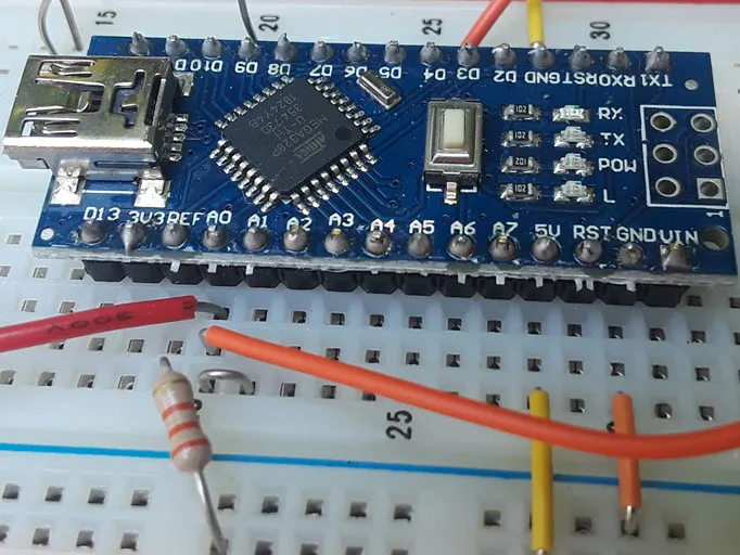
The Nano is a miniaturized replacement for the Uno. It uses a surface-mount version of the microcontroller so that the entire development board is only slightly larger than an Atmel 328P IC. Other than having a mini USB connector, the Nano board – like the Uno, contains similar additional devices such as a reset button, 5-volt and 3.3–volt regulator outputs, and the four LEDs. The Nano has 30 pins which can directly plug into a breadboard but is slightly larger in width than an IC, so it takes up some extra board space. The extra width covers three holes on one side, and two on the other side of the gap in the middle of a normal breadboard. It still leaves two breadboard holes connected to each pin on one side of the gap, and three holes on the other side. Both the Uno and Nano will work for projects in this book, but as previously mentioned, the Nano is more wiring friendly. A note of warning, however, there is header pin incompatibility between the two boards, but luckily most Nano boards have the pin designation stencilled near each pin. The Nano is shown plugged into a breadboard:
Figure 1.5: The Arduino Nano plugged into breadboard power rails
Connecting the 5-volt and ground pins of the Nano to the breadboard power rails allow you to use the computer’s USB port to power breadboard circuits. If you have a 5-volt power supply, after uploading your code, you can disconnect from the computer’s USB port and run the Nano and additional breadboard circuits from your supply. The Nano also has a pin marked Vin which will allow you to use the Nano board’s voltage regulator for supply voltages up to 12-volts. Take care not to exceed 5-volts on any I/O pins. When using a supply voltage higher than 5-volts connected to the Vin pin, the 5-volt and ground pins can be used to provide regulated power to the breadboard power rails.
Both digital and most analogue pins can be set for input or output. Sometimes interfacing circuits must be used if higher than recommended output currents are needed. The average output current per pin is recommended to be 20 mA with an absolute maximum of 40 mA.
Additionally, some of the analogue pins on the Nano can provide more digital I/O, but digital pins cannot be switched to analogue. The Nano also provides two additional analogues only pins (A6 and A7.) The analogue pins are for connecting to an Analogue to Digital Converter (ADC) in the IC. It will represent an analogue signal in 1024 steps so that input values are assigned numerical values between 0 and 1023. While there is no Digital to Analogue Converter (DAC) in the Arduino IC, the analog output is simulated by using Pulse Width Modulation (PWM). In a true DAC, the analog output steps would...
Table of contents
Cover Page
Title Page
Copyright Page
About the Author
About the Reviewer
Acknowledgement
Preface
Errata
Table of Contents
1. A Bit about the Arduino
2. Digital Function Implementation
3. Designing Functional Computer Circuits
4. Memory Devices
5. Registers and Numbers
6. Counters
7. Multiplexing and Demultiplexing
8. Addresses, Specialized Counters, and Serial Monitor Interaction
9. Random Numbers
10. Interactive I/O
11. Capstone Project
Appendix : Debounced Switches
Frequently asked questions
Yes, you can cancel anytime from the Subscription tab in your account settings on the Perlego website. Your subscription will stay active until the end of your current billing period. Learn how to cancel your subscription
No, books cannot be downloaded as external files, such as PDFs, for use outside of Perlego. However, you can download books within the Perlego app for offline reading on mobile or tablet. Learn how to download books offline
Perlego offers two plans: Essential and Complete
Essential is ideal for learners and professionals who enjoy exploring a wide range of subjects. Access the Essential Library with 800,000+ trusted titles and best-sellers across business, personal growth, and the humanities. Includes unlimited reading time and Standard Read Aloud voice.
Complete: Perfect for advanced learners and researchers needing full, unrestricted access. Unlock 1.5M+ books across hundreds of subjects, including academic and specialized titles. The Complete Plan also includes advanced features like Premium Read Aloud and Research Assistant.
Both plans are available with monthly, semester, or annual billing cycles.
We are an online textbook subscription service, where you can get access to an entire online library for less than the price of a single book per month. With over 1.5 million books across 990+ topics, we’ve got you covered! Learn about our mission
Look out for the read-aloud symbol on your next book to see if you can listen to it. The read-aloud tool reads text aloud for you, highlighting the text as it is being read. You can pause it, speed it up and slow it down. Learn more about Read Aloud
Yes! You can use the Perlego app on both iOS and Android devices to read anytime, anywhere — even offline. Perfect for commutes or when you’re on the go. Please note we cannot support devices running on iOS 13 and Android 7 or earlier. Learn more about using the app
Yes, you can access Digital Electronics with Arduino by Bob Dukish in PDF and/or ePUB format, as well as other popular books in Computer Science & Systems Architecture. We have over 1.5 million books available in our catalogue for you to explore.