- 274 pages
- English
- ePUB (mobile friendly)
- Available on iOS & Android
eBook - ePub
GIS for Water Resource and Watershed Management
About this book
The use of GIS, and its application for solving environmental problems is growing rapidly. This powerful set of tools can be used to great effect in hydrological modeling, environment and habitat assessments, ecosystem studies, monitoring of wetlands and forested watersheds, urban studies, agricultural impact assessment and much more. GIS for Water
Trusted by 375,005 students
Access to over 1.5 million titles for a fair monthly price.
Study more efficiently using our study tools.
Information
Topic
Physical SciencesSubtopic
Civil EngineeringCHAPTER 1
Channel Network Delineation and Watershed Segmentation in the TOPAZ Digital Landscape Analysis System
Lawrence W. Martz and Jurgen Garbrecht
INTRODUCTION
Research over the past decade has demonstrated the feasibility of extracting topographic information of hydrological interest directly from digital elevation models (DEM). Techniques are available for extracting slope properties, catchment areas, drainage divides, channel networks and other data (Jenson and Domingue, 1988; Mark, 1988; Moore et al., 1991; Martz and Garbrecht, 1992). These techniques are faster and provide more precise and reproducible measurements than traditional manual techniques applied to topographic maps (Tribe, 1991). As such, they have the potential to greatly assist in the parameterization of hydrologic surface runoff models, especially for larger watersheds (i.e., >10 km2) where the manual determination of drainage network and subwatershed properties is a tedious, time-consuming, error-prone, and often highly subjective process. The automated techniques also have the advantage of generating digital data that can be readily imported and analyzed by Geographic Information Systems (GIS).
This chapter presents an overview and discussion of the original DEDNM (Digital Elevation Drainage Network Model) computer program developed to measure drainage network and subcatch-ment parameters directly from a DEM. A detailed discussion of the original program structure and algorithms is available in Martz and Garbrecht (1992). Improvements and modifications to the program continue to be made, although the essential approach to drainage analysis remains largely unchanged. DEDNM now functions as the core component in a more comprehensive digital landscape analysis system known as TOPAZ (TOpographic PArameteriZation) (Garbrecht and Martz, 1999).
DEDNM OVERVIEW
The main purpose of the program is to provide an automated, rapid, and reproducible evaluation of the topographic properties of large watersheds by processing raster DEMs. The primary application target for the program is the parameter determination for hydrologic surface runoff models. The following general objectives guided the program development:
- Program input should be DEMs that are both commonly available to hydrologists and represent the land surface in sufficient detail for hydrologic analysis.
- The program should not be limited by the nature of the topography represented in the DEM and should be applicable to both high and low relief terrain.
- The program should extract all topographic and topologic drainage network and watershed properties relevant to the parameterization of hydrologic surface runoff models.
- The program should incorporate established and proven algorithms from earlier research, and supplement these with new algorithms as required.
- The program output should be structured so that it can be used directly for hydrologic model parameterization and be readily imported by a GIS.
The program first preprocesses the DEM to remove depressions and flat areas without modifying other parts of the DEM. Flow simulation algorithms are then applied to determine the catchment area of each grid cell, and to define the boundaries of the watershed to be analyzed. A continuous, unidirectional channel network is delineated by selecting all grid cells with a catchment area in excess of a user-specified critical source area.
Network evaluation involves tracing the course of the channels in the previously defined watershed, and identifying the junctions in the network. Channel tracing is directed by flow direction codes generated in the flow simulation analysis. The channels are traced initially to order the network according to the Strahler system, and to determine the length of each network link and the spatial coordinates of its upstream and downstream end. These data are used, in turn, to calculate the slope and catchment area properties of each link, and the number and average properties of the channel segments of each Strahler order. The channels are traced again to assign unique identification numbers to each node in the network. These node numbers are used to associate link, node, and subwatershed data, and can also be used to optimize flow routing in hydrologic models. A final trace is used to identify the subwatersheds of each source node and of the left and right banks. The individual subwatershed areas are then evaluated to determine their slope and overland flow travel distances.
The program generates both tabular and raster output (Table 1.1). The tabular output gives the watershed and drainage network properties of the total drainage network and of the individual network links. The raster output provides maps of the watershed and drainage network components which can be imported into a GIS, registered to other data layers, and used as templates to extractadditional, hydrologically-relevant information (i.e., soil type, land cover, climate, etc.) for individual subwatersheds and network components.
TABLE 1.1. Summary of the Major DEDNM Program Outputs
DEDNM is coded in FORTRAN–77. It is modular to allow easy modification and reorganization to meet specific needs. Each major operation is performed by a set of subroutines called from the main program. Program input is a raster DEM in a standardized format, DEM parameters (i.e., number of rows and columns, elevation range, etc.) and user-specified job parameters that control processing and output. DEDNM keeps all data in dynamic memory during execution to minimize time-consuming I/O operations. While memory requirements are minimized by performing all computations on and storing all elevations as integer data, the processing of large DEMs can create significant memory demands. An option to aggregate the DEM to a coarser grid cell size is provided to permit operation in limited memory or to permit more rapid preliminary analyses of large DEMs. DEDNM can be compiled to run on any hardware platform and, provided sufficient memory is available, can be easily configured to process any size of DEM.
DEM PREPROCESSING
The design objectives for DEDNM emphasize the analysis of generally available DEMs which represent landscapes at a resolution that allows the extraction of hydrologic variables. The 7.5-minute DEMs distributed by the United States Geological Survey (USGS) are typical of such data. They provide elevation values in 1 m increments for 30 m grid cells over areas corresponding to USGS 7.5-minute quadrangles. Much of the United States is now covered by such DEMs, and coverage continues to increase. DEMs with the same general structure and order of resolution are provided by other national jurisdictions and can be generated from SPOT data (Quinn et al., 1991; Tribe, 1991).
A fundamental problem in using DEMs of this order of resolution for hydrologic analysis is the presence of sinks in the data. Sinks are grid cells with no neighbors at a lower elevation and, consequently, with no downslope flow path to a neighbor. By this definition, sinks occur on both flat areas and in closed depressions. Sinks are quite common in DEMs with a spatial and vertical resolution similar to that of the USGS 7.5-minute DEMs. They also tend to be more common in low relief terrain than in high relief terrain. While a few of these sinks may represent real landscape features, the majority are spurious features which arise from interpolation errors during DEM generation, truncation of interpolated values on output, and the limited spatial resolution of the DEM grid (Mark, 1988; Fairchild and Leymarie, 1991; Martz and Garbrecht, 1992).
Figure 1.1 shows the spatial distribution of sinks in a DEM of an 84 km2low relief watershed used as a test data set in developing DEDNM (Garbrecht and Martz, 1997). The DEM elevations are in 0.9 m (3 ft) increments for 30 m grid cells. Ten percent of the watershed is covered by sinks, of which 25% are in closed depressions and 75% are on flat areas. The sinks are concentrated along valley bottoms where local slopes are gentle. The banded appearance of many of the flat areas suggests that they are artifacts of the limited vertical resolution of the DEM.
The ability to simulate flow across sinks is essential for effective hydrologic analysis of DEMs of this type. DEDNM provides this capability through a two-phase operation which has the same effective result as the flow modification method of Jenson and Domingue (1988). The first phase involves filling all closed depressions to the elevation of their local outlet using the method of Martz and de Jong (1988). The subwatershed of a depression is delineated and the lowest outlet on the edge of this area is identified. The elevation of all cells within the subwatershed and below the elevation of the lowest outlet are raised to the outlet elevation to simulate depression filling (Figure 1.2). Complex, nested, or truncated depressions are readily evaluated by the filling algorithm. Subtracting elevations in the original DEM from those in the DEM modified by depression-filling gives the location, spatial extent, and depth of depressions.
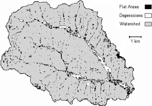
Figure 1.1. Type and spatial extent of sinks in DEM of Bill’s Creek watershed in southwestern Oklahoma.
The second phase imposes relief on all flat areas (both those created by depression-filling and those inherent to the DEM) to permit the unambiguous definition of flow paths across these areas. Two assumptions are implicit to this operation: (1) flat areas are not truly level, but have relief that is simply not detectable at the resolution of the DEM, and (2) this relief directs flow entering or originating on the apparent flat area along a reasonably direct path over the flat area to a point on its perimeter where a downward slope is available. Relief is imposed by adding an elevation increment of 1/1000th of the vertical resolution of the DEM to each cell with no neighbor at a lower elevation (Figure 1.2). This is repeated until no flat areas remain. This approach to the treatment of sinks is superior to the use of prior smoothing to remove sinks because it focuses directly on problem areas without reducing the information content of the DEM elsewhere. It also relies on an assessment of local boundary conditions that bear directly on flow patterns.
The current version of DEDNM incorporated into the TOPAZ digital landscape analysis system introduced two significant improvements for the treatment of depressions and flat areas. These improvements allow the breaching (i.e., lowering) of the outlet of some depressions and apply a two-phase relief imposition algorithm to direct flow across flat areas simultaneously away from higher and toward lower surrounding terrain (Garbrecht and Martz, 1997).
FLOW VECTOR AND DRAINAGE AREA ANALYSIS
Following the preprocessing operation, a flow vector code is assigned to each grid cell using the D8 method (Fairchild and Leymarie, 1991). The flow vector indicates the direction of the steepest downward slope to an immediately neighboring cell. Where more than one downward slope maxima exist, the flow vector is arbitrarily assigned to indicate the direction of the maximum first encountered. At cells on the edge of the defined DEM (i.e., cells in the outer rows and columns, or adjacent to a cell with a missing elevation value), the flow vector points away from the defined DEM if no other downward slope to a neighbor is available. All flow originating on or entering a cell is assumed to move in the direction indicated by the flow vector, and no divergent flow out of a cell is accommodated.
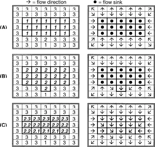
Figure 1.2. DEM preprocessing by DEDNM. Elevations (left column) and associated flow paths (right column) are shown for: (A) original DEM with depression; (B) DEM with flat area created by depression filling; (C) DEM with relief imposed on flat area (for simplicity of illustration, an elevation increment of 1/10th is used).
The catchment area of each grid cell is determined using the method of Martz and de Jong (1988). The flow vectors are used to follow the path of steepest descent from each cell to the edge of the DEM, and the catchment area of each cell along this path is incremented by one. After a path has been initiated from each cell, the catchment area value accumulated at each cell gives the number of upstream cells which contribute overland flow to that cell (Figure 1.3).
The boundary of the watershed to be analyzed is also determined from the flow vectors. The user specifies the location of the grid cell at watershed outlet, and all grid cells which contribute overland flow to the outlet cell are identified. This provides a mask of the watershed that is used for subsequent operations.
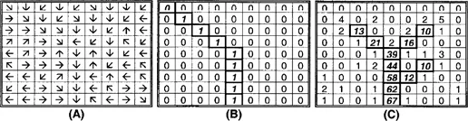
Figure 1.3. Catchment area determination by DEDNM: (A) flow vectors at each DEM cell; (B) catchment area at each DEM cell after the first flow path (highlighted) has been traced from the upper-left cell; (C) catchment area at each DEM cell after flow paths have been traced from all cells. Highlighted cells in (C) are those classified as channels using a critical source area of 10 cells.
CHANNEL NETWORK ANALYSIS
The channel network within the watershed is delineated from the catchment area grid. All cells with a catchment area greater than a user-specified critical source area are classified as part of the channel network. This yields a fully connected, unidirectional network. However, the network may contain some very short exterior links which represent valley side indentations, gully outlets, and other features that normally would not be classified as part of the channel network. The network is p...
Table of contents
- COVER PAGE
- TITLE PAGE
- COPYRIGHT PAGE
- ABOUT THE EDITOR
- CONTRIBUTORS
- ACKNOWLEDGEMENTS
- INTRODUCTION GIS FOR WATER RESOURCES AND WATERSHED MANAGEMENT
- CHAPTER 1 CHANNEL NETWORK DELINEATION AND WATERSHED SEGMENTATION IN THE TOPAZ DIGITAL LANDSCAPE ANALYSIS SYSTEM
- CHAPTER 2 ASSESSING THE PERFORMANCE OF AUTOMATED WATERSHED SEGMENTATION FROM DIGITAL ELEVATION MODELS
- CHAPTER 3 DEVELOPMENT OF A BASIN GEOMORPHIC INFORMATION SYSTEM USING A TIN-DEM DATA STRUCTURE
- CHAPTER 4 BASINSOFT, A COMPUTER PROGRAM TO QUANTIFY DRAINAGE BASIN CHARACTERISTICS
- CHAPTER 5 DERIVING STREAM CHANNEL MORPHOLOGY USING GIS-BASED WATERSHED ANALYSIS
- CHAPTER 6 GIS MODELING AND VISUALIZATION OF THE WATER BALANCE DURING THE 1993 MIDWEST FLOOD
- CHAPTER 7 SELECTION, DEVELOPMENT, AND USE OF GIS COVERAGES FOR THE LITTLE WASHITA RIVER RESEARCH WATERSHED
- CHAPTER 8 REGIONAL CHARACTERIZATION OF INLAND VALLEY AGROECOSYSTEMS IN WEST AND CENTRAL AFRICA USING HIGH-RESOLUTION REMOTELY SENSED DATA
- CHAPTER 9 WATERSHED CHARACTERIZATION BY GIS FOR LOW FLOW PREDICTION
- CHAPTER 10 EVALUATION OF THE ALBEMARLE-PAMLICO ESTUARINE STUDY AREA UTILIZING POPULATION AND LAND USE INFORMATION
- CHAPTER 11 APPLICATION OF GIS AND REMOTE SENSING FOR WATERSHED ASSESSMENT
- CHAPTER 12 DEVELOPMENT OF A DATABASE FOR LAKE ECOSYSTEM STUDIES: LINKING GIS WITH RDBMS
- CHAPTER 13 HISTORICAL AERIAL PHOTOGRAPHS AND A GEOGRAPHIC INFORMATION SYSTEM (GIS) TO DETERMINE EFFECTS OF LONG-TERM WATER LEVEL FLUCTUATIONS ON WETLANDS ALONG THE ST. MARYS RIVER, MICHIGAN, USA
- CHAPTER 14 WATERSHED-BASED EVALUATION OF SALMON HABITAT
- CHAPTER 15 PHYSICAL CHARACTERIZATION OF THE NAVARRO WATERSHED FOR HYDROLOGIC SIMULATION
- CHAPTER 16 HYDROLOGIC MODELING USING REMOTELY SENSED DATABASES
- CHAPTER 17 TECHNOLOGICAL ADVANCES IN AUTOMATED LAND SURFACE PARAMETERIZATION FROM DIGITAL ELEVATION MODELS
- CHAPTER 18 AERIAL PHOTOINTERPRETATION OF HAZARDOUS WASTE SITES: AN OVERVIEW
- CHAPTER 19 REMOTE SENSING AND GIS FOR SITE-SPECIFIC FARMING
Frequently asked questions
Yes, you can cancel anytime from the Subscription tab in your account settings on the Perlego website. Your subscription will stay active until the end of your current billing period. Learn how to cancel your subscription
No, books cannot be downloaded as external files, such as PDFs, for use outside of Perlego. However, you can download books within the Perlego app for offline reading on mobile or tablet. Learn how to download books offline
Perlego offers two plans: Essential and Complete
- Essential is ideal for learners and professionals who enjoy exploring a wide range of subjects. Access the Essential Library with 800,000+ trusted titles and best-sellers across business, personal growth, and the humanities. Includes unlimited reading time and Standard Read Aloud voice.
- Complete: Perfect for advanced learners and researchers needing full, unrestricted access. Unlock 1.5M+ books across hundreds of subjects, including academic and specialized titles. The Complete Plan also includes advanced features like Premium Read Aloud and Research Assistant.
We are an online textbook subscription service, where you can get access to an entire online library for less than the price of a single book per month. With over 1.5 million books across 990+ topics, we’ve got you covered! Learn about our mission
Look out for the read-aloud symbol on your next book to see if you can listen to it. The read-aloud tool reads text aloud for you, highlighting the text as it is being read. You can pause it, speed it up and slow it down. Learn more about Read Aloud
Yes! You can use the Perlego app on both iOS and Android devices to read anytime, anywhere — even offline. Perfect for commutes or when you’re on the go.
Please note we cannot support devices running on iOS 13 and Android 7 or earlier. Learn more about using the app
Please note we cannot support devices running on iOS 13 and Android 7 or earlier. Learn more about using the app
Yes, you can access GIS for Water Resource and Watershed Management by John G. Lyon in PDF and/or ePUB format, as well as other popular books in Physical Sciences & Civil Engineering. We have over 1.5 million books available in our catalogue for you to explore.