- 304 pages
- English
- ePUB (mobile friendly)
- Available on iOS & Android
eBook - ePub
Protection Devices and Systems for High-Voltage Applications
About this book
This publication discusses general problems related to the structure of current overload protection systems in high voltage (HV) electrical installations and introduces a family of new devices based on reed switch contacts, solid-state units, hybrid technology and automatic systems based on these components. It highlights their application in high
Trusted by 375,005 students
Access to over 1.5 million titles for a fair monthly price.
Study more efficiently using our study tools.
Information
1
Problems of Overload and Spark Protection Systems for High Power RF Generators, Lasers, and Radar
1.1 COMMON PROBLEMS OF HV EQUIPMENT
High voltage (HV) equipment (10-100 kV) has become very popular over the last few years. It is utilized in military and civil radar stations, powerful signal transmitters for communication, broadcasting and TV systems, technological lasers, X-ray devices, powerful electronic and ion devices, devices for inductive heating and melting of metals, technological electron accelerators for materials irradiation, electro-physical and medical equipment, and industrial microwave ovens, among others.
Despite considerable success in each of these fields, the problem of current overload protection (level current trip) of such devices, caused by HV circuit insulation breakdowns or breakdowns in the high voltage devices, still remains acute. The first is related to unfavorable conditions that cause moisture and dust penetration into the equipment, and the second to unpredictable internal breakdowns in high voltage vacuum electronic elements (klystrons, tetrodes, etc.) or semiconductor elements (HV rectifier).
Current overload protection in such devices is usually resolved by inclusion of current sensors and electronic relays into the low voltage (LV) or grounded circuits. However, such protection is not necessarily efficient and implies some problems:
- Complicated devices include more than one HV circuit, often having different potential relative to ground, as well as different internal resistance and operational currents. This produces difficulties in adjustment of the sensor connected to the common ground circuit and is not appropriate for equal protection efficiency of all these circuits.
- The possibility of connecting to an emergency current sensor located only in the common ground circuit imposes certain restrictions on the system design, forcing the designers to use more complex and expensive devices.
- In this matter, sensitivity of the current sensor is dependent on grounding circuit quality, which is particularly severe in mobile equipment. However, this connection enables high voltage overpass to a low voltage circuit in emergency mode. All this has an effect on the equipment and maintenance personnel.
- Internal high voltage power supplies (PS) have a powerful filter with reactive elements used for leveling the high voltage rectifier pulsations. If such power supplies are disconnected from the low voltage power supply net (220, 380, 440 V), the reactive filter elements will still replenish the arc in the breakdown point up to their complete discharge. On the other hand, a “crowbar” connecting to the HV source at the high voltage side, rather than disconnection at the LV side, will cause a heavy overload of the high voltage rectifier and the feeding transformer elements. In this way, their risk of failure will drastically increase.
- The use of protective shorting by gas discharge thyratrons or vacuum-triggered spark gaps yields more problems because of the extremely short time (a few microseconds) during which discharge current flow is permitted via such devices. In continuous operation, very small currents are permitted in such devices. For example, in a HY-3201 device with parameter values as high as Uanode =32kV and Ianode = 20kA, the permitted average anode current is only 0.5A. On the one hand, it is quite difficult to enable discharge of such powerful filter elements within fractions of microseconds. On the other hand, considerable discharge currents are not permitted via standard high-capacity filter condensers. They can be discharged only via limiting resistance, namely within time intervals longer than a few microseconds. Moreover, the filament circuit of the thyratrons must be permanently powered, similar to standard high-power electronic tubes (6.3 V, 18A).
- When a PS with a powerful step-up transformer, rectifier and high capacity ripple filter at the output is connected to equipment, a strong current spike occurs, causing the overloading of all the above elements.
This generates a need for selective tuning-out of the emergency current sensor, which considerably lowers protection efficiency.
This book describes a new generation of universal HV equipment protection systems to deal with overcurrent situations and internal breakdowns. A set of units comprises a series of High Voltage Interface Relays or RG (“Relay of Gurevich”), a series of low voltage solid state contactors and a series of HV thyristor short circuiting devices, and other devices.
We offer system designers a set of universal units from which a variety of highly efficient protection systems, customized to specific needs, can be assembled.
1.2 INTERFACE RELAYS
Technical difficulties caused by the presence of functional components isolated from each other, not permitting direct connection owing to a high difference of potentials, are encountered when designing systems for control and protection against emergency conditions (over current, sparks) in modern power HV equipment. To guarantee information and electrical compatibility as well as to implement the required algorithms for interaction of functional components of equipment, special control instruments are required that have been called “interface relays” or “insulating interfaces” in the technical literature. The general principle of design of these instruments is the presence of a special galvanic decoupling unit between the receiving and final controlling systems of the relay.
Interface relays with a working voltage of more than 10 kV have the greatest interest for these areas of engineering, to which the present study is devoted.
In the design of devices classified as interface relays, some of the widely-used physical principles may not be used in electrical relays of other types.
It is well-known that any electromagnetic relay has a specific level of isolation of the output circuits from the input circuits, i.e., it functions secondarily as an interface relay. However, in ordinary relays, this function is not decisive and is not at all considered in the existing system of classification. In the interface relay, the property of galvanic decoupling of the circuits has been repeatedly intensified, and the parameters of the galvanic decoupling unit are decisive from the standpoint of the function performed by this relay. On the other hand, the parameters associated with switching capacity are secondary and, significantly, can be interface relays with the same level of galvanic decoupling. In this regard, an artificial assignment of interface relays to existing classes does not seem to be expedient. Rather, it seems more appropriate to classify them as a separate type of electrical equipment having an intrinsic structure based mostly on classification according to characteristics of the galvanic decoupling unit. For example, according to the decoupling voltage level:
| - | low level (to 10 kV); |
| - | medium level (10 to 100 kV); |
| - | high level (above 100 kV). |
According to principle of action:
| - | opto-electronic, |
| - | pneumatic, |
| - | radio-frequency, |
| - | electrohydraulic, |
| - | transformer, |
| - | ultrasonic, |
| - | electromagnetic, and with mechanical transmission. |
According to speed:
| - | super fast (up to 100 µsec); |
| - | fast (100 µsec to 2 ms); |
| - | inertial (above 2 ms). |
Although such classification may seem arbitrary, it fully reflects the most important properties of interface relays that have a decisive effect on the functions performed by them.
The simplest interface relays of the opto-electronic type typically consists of a light-emitting element (LED) built into the semiconductor structure (power SCR, triac) or LED and matching low power photothyristor or phototransistor in switching mode, mounted close together and optically coupled within a light-excluding package having a galvanic decoupling voltage up to 4 kV.
Some companies (EAC Electronics, Aleph, Crydom, Magnecraft) are producing high voltage reed relays for commutation voltage up to 10 -12 kV DC, and therefore, have a galvanic decoupling voltage on the same level. All these relays are intended for use only in DC circuits under normal climatic conditions and have no reserves for withstanding voltage.
In order to significantly increase the galvanic decoupling level of interface relays of the opto-electronic type, a fiber optic cable of appropriate length is installed between the LED and photo-receiving elements. These relays are also equipped with an electronic pulse shaper and an electronic amplifier. At a length of about 1 to 3 meters of fiber optic cable connecting the transmitting and receiving units, the galvanic decoupling voltage ensured by the interface relay can reach 40 kV and more.
Interface relays of the opto-electronic type have also found application in electrical power configurations in which the transmitting and receiving units are connected by hollow porcelain insulators of fairly large dimensions that are equipped with a built-in optical system. Such interfaces are used in 110 – 330 kV power networks to control the drives of high voltage circuit breakers as a device for protecting shunt capacitor batteries, etc.
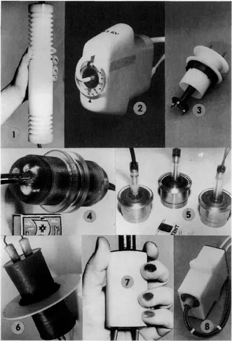
Figure 1.1 Some reed switch-based HV interfaces developed by the author in the years 1977-1994.
The developmental trends of interface relay technology suggest the use of opto-electronic systems as the prevailing design principle for galvanic decoupling units. It is agreed that the most important characteristic feature of opto-electronic systems is their noise immunity and insensitivity to electromagnetic fields. However, what is not considered here is that, in additional to the fiber optic line itself and the output actuator, such a system includes shaper of light pulses on the transmitting and electronic amplifier with triggering units on the receiving end that are generally based on microcircuitry.
It is precisely these elements, which have low activation levels, that are damaged by pulse noise on the side of high voltage power equipment (interferences, spikes and high voltage discharges), which negates the main advantage of opto-electronic systems.
Moreover, the optical fibers themselves are subject to a severe negative effect of ionizing radiation and external mechanical influence (it is a very important for military applications).
The arrangement of input and output circuits of such systems should be widely spaced (optical fiber length is 1 – 2 meters for voltage 40 – 150 kV), and it is this factor that determines the overall dimensions of interface unit.
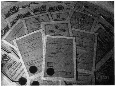
Figure 1.2 Patents and certificates of authorship pertaining to the HV reed switch-based interfaces.
All this indicates that the preferred use of an opto-electronic galvanic decoupling unit in interface relays is not always warranted, and it sometimes is merely the consequence of stereotypical thinking of developers or a peculiar technical style.
In 1985, the Brown Bowery Co. started a special program for development of the “Sigma-Switch” interface relays. The development and introduction of essentially new interface relays were contemplated together with the usual opto-electronic system, especially with a galvanic deco...
Table of contents
- Front Cover
- Half Title
- POWER ENGINEERING
- Title Page
- Copyright
- Contents
- Series Introduction
- Preface
- Acronyms
- 1 Problems of Overload and Spark Protection Systems for High Power RF Generators, Lasers, and Radar
- 2 High-Voltage Interface RG-series Relays
- 3 High-Voltage Switching Devices
- 4 Low-Voltage Switching Devices for High-Voltage Power Supply
- 5 Applications for Power Engineering
- 6 Applications for Powerful Radio-Electronic Equipment
- 7 High-Voltage Devices for Industrial Applications
- Appendix A: Selected Publications by the Author
- Appendix B: Some Types of RG-relays with a Special Characteristics
- Appendix C: Environmental Tests of RG-relays for MIL-STD-202 Requirements
- Appendix D: Components Recommended for Use in HV Protection Devices
- Appendix E: Insulation Materials for Production of RG-relays
- Appendix F: Engineering Equations for Calculations of Magnetic Conductivity in Magnetic Circuits and Electrical Fields for Some Forms of Electrodes
- Index
Frequently asked questions
Yes, you can cancel anytime from the Subscription tab in your account settings on the Perlego website. Your subscription will stay active until the end of your current billing period. Learn how to cancel your subscription
No, books cannot be downloaded as external files, such as PDFs, for use outside of Perlego. However, you can download books within the Perlego app for offline reading on mobile or tablet. Learn how to download books offline
Perlego offers two plans: Essential and Complete
- Essential is ideal for learners and professionals who enjoy exploring a wide range of subjects. Access the Essential Library with 800,000+ trusted titles and best-sellers across business, personal growth, and the humanities. Includes unlimited reading time and Standard Read Aloud voice.
- Complete: Perfect for advanced learners and researchers needing full, unrestricted access. Unlock 1.5M+ books across hundreds of subjects, including academic and specialized titles. The Complete Plan also includes advanced features like Premium Read Aloud and Research Assistant.
We are an online textbook subscription service, where you can get access to an entire online library for less than the price of a single book per month. With over 1.5 million books across 990+ topics, we’ve got you covered! Learn about our mission
Look out for the read-aloud symbol on your next book to see if you can listen to it. The read-aloud tool reads text aloud for you, highlighting the text as it is being read. You can pause it, speed it up and slow it down. Learn more about Read Aloud
Yes! You can use the Perlego app on both iOS and Android devices to read anytime, anywhere — even offline. Perfect for commutes or when you’re on the go.
Please note we cannot support devices running on iOS 13 and Android 7 or earlier. Learn more about using the app
Please note we cannot support devices running on iOS 13 and Android 7 or earlier. Learn more about using the app
Yes, you can access Protection Devices and Systems for High-Voltage Applications by Vladimir Gurevich in PDF and/or ePUB format, as well as other popular books in Technologie et ingénierie & Ingénierie de l'électricité et des télécommunications. We have over 1.5 million books available in our catalogue for you to explore.