- 300 pages
- English
- ePUB (mobile friendly)
- Available on iOS & Android
eBook - ePub
Fundamentals of Rail Vehicle Dynamics
About this book
Fundamentals of Rail Vehicle Dynamics lays a foundation for the design of rail vehicles based on the mechanics of wheel-rail interaction as described by the equations of motion. The author advances simple models to elucidate particular challenges and demonstrate innovative systems while using analytical studies to examine novel design concepts. Rather than focusing on a "typical" set of parameters, the book discusses the issues associated with the complete range of parameters available, concentrating on the configuration and parametric design of the bogie in relation to steering, dynamic response, and stability. This is an excellent reference for designers and researchers involved vehicle development.
Trusted by 375,005 students
Access to over 1.5 million titles for a fair monthly price.
Study more efficiently using our study tools.
Information
1
Basic Concepts
1.1 Introduction
The railway train running along a track is one of the most complex dynamical systems in engineering. It has many degrees of freedom, the interaction between wheel and rail involves both complex geometry of wheel tread and rail head and nonconservative forces generated by relative motion in the contact area, and there are many non-linearities.
The long history of railway engineering provides many practical examples of dynamical problems which have degraded performance and safety. The two essential features of operation, running in a train of vehicles and guidance by the track, cause problems which are unique to railways. Inadequate guidance on curves results in high lateral forces between wheel and rail, rapid wear of wheels and rails and the possibility of derailment. Dynamic and static instabilities, and excessive response to track irregularities and other features of track geometry, can result in poor ride quality and high stresses and can contribute to derailment. Operation in a train involves the control of forces acting between the vehicles in the train as the propulsive and braking forces are varied in response to the train traversing hills and valleys. High frequency interaction between wheel and rail can lead to damage to the contacting surfaces and corrugation of the rails, and excessive noise and vibration.
The dynamics of the railway vehicle represents a balance between the forces acting between the wheel and the rail, the inertia forces and the forces exerted by the suspension and articulation. Of these, the basic characteristics of the wheel-rail interface such as friction, geometry, and the elasticity in the contact area are hardly under the control of the designer. But the configuration, suspension and forms of articulation can be varied over a wide range of possibilities, limited mainly by the degree of complexity considered acceptable for each application. The objective of suspension design is, therefore, to control the motion of the railway vehicle so that good ride quality is achieved, at the same time dynamic loads and the tendency to derail are reduced to acceptable levels, whilst running on track with geometry that is economically acceptable.
In a complete model of the dynamics of a railway vehicle, the vehicle is considered to be assembled from wheelsets, car bodies and intermediate structures which are flexible, and which are connected by components such as springs and dampers. Similarly, the vehicle is considered to run on a track which has a complex structure with elastic and dissipative properties. Each major component has six rigid body degrees of freedom plus additional degrees of freedom representing the elastic distortion of the component. In the latter case, these additional degrees of freedom might represent a finite element model of the structure or a series of natural modes of vibration. The track can be modelled as a continuous structure with a moving interface at the points of contact, where the interaction between wheel and rail is dependent on the relative motion. This kind of model, with varying assumptions, is provided by various computer software packages which are used in the engineering design and analysis of railway vehicles. So, one objective of the study of the dynamics of railway vehicles is the development of sufficiently detailed and validated mathematical models that permit the simulation of the actual motion, on a specified stretch of line, so that the performance of a specific design can be analysed, or a particular incident recreated. Thus, by simulation, the overall performance of an existing or projected vehicle can be checked and design decisions made.
A second objective of the study of railway vehicle dynamics is to develop analytical or numerical models describing the mechanics of various phenomena by the simplest model possible. These can be used to explore new suspension and vehicle concepts and to develop a basis for physical understanding and insight. Ideally, not only analysis but synthesis is required in which various possibilities for design are exposed. Simpler models are typically generated by simplifying assumptions and in this book, concerned with guidance and stability, these are that
- the vehicle has a longitudinal plane of symmetry (parallel to the direction of motion on straight track) making it possible, under certain conditions, to separate equations governing those motions which are symmetric with respect to the plane of symmetry from those which govern anti-symmetric motions;
- variations in longitudinal motion are not considered so that the vehicle moves at constant forward speed;
- the motions of interest are at low frequencies and, in most cases, flexibility of components can be neglected.
It is the objective of this chapter to explain the basic concepts of stability and guidance of railway vehicles as a preliminary to more detailed mathematical analysis.
1.2 The Railway Wheelset
The basic unit of a railway vehicle is the wheelset, Figure 1.1. The conventional wheelset of today has the following features: it consists of two wheels fixed on a common axle, so that each wheel rotates with a common angular velocity and a constant distance between the two wheels is maintained. Flanges are provided on the inside edge of the treads and the flange-way clearance allows, typically, ± 7–10 mm of lateral displacement to occur before flange contact. Whilst many wheelsets commence life with purely coned treads, typically coned at 1/20 or 1/40, these treads wear rapidly in service, so that the treads come to possess curvature in the transverse direction. Similarly, rails also possess curvature in the transverse direction. All these features contribute to the behaviour of the railway vehicle as a dynamic system, and it is important to consider their purpose.
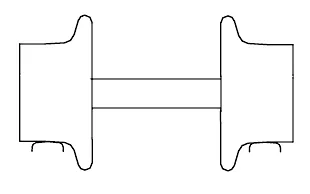
Figure 1.1 Railway wheelset.
The conventional railway wheelset has a long history [1] and seems to have evolved by a process of trial and error. Naturally, in the pioneering days of the early railways most attention was concentrated on reducing rolling resistance so that the useful load that could be hauled by horses could be multiplied. Another major problem was the lack of strength and resistance to wear of the materials then available. Moreover, the level of adhesion between rolling wheel and the track was unknown. As a result, many possibilities were tried. An obvious step was to fit wheels with cylindrical treads. However, if the wheels are fixed on the axle and the treads are intended to be cylindrical very slight errors in parallelism would induce large lateral displacements which would be limited by flange contact. There is no guidance until flange contact and thus a wheelset with cylindrical treads tends to run in continuous flange contact. The position of the flange, either inside or outside the rails, was controversial well into the nineteenth century. Nor was there agreement as to whether the wheels should be rigidly fixed to an axle or free to revolve on the axle, though the usual practice seemed to be that wheels were fixed to the axle. The play allowed between wheel flange and rail was initially minimal. In the early 1830s the flangeway clearance was opened up with the objective of reducing the lateral forces between wheel and rail.
A further important point is that the geometry of the wheel and rail as it has evolved is particularly favourable for the method of switching which involves a minimum of moving parts and only small gaps in the running surfaces of the rails.
It is not known when coning of the wheel tread was first introduced. It would be natural to provide a smooth curve uniting the flange with the wheel tread, and wear of the tread would contribute to this. Moreover, once wheels were made of cast iron, taper was normal foundry practice. The purpose of coning was partly to reduce the rubbing of the flange on the rail, and partly also to ease the motion of the vehicle in curves.
A wheelset with coned wheels in a curve can maintain a pure rolling motion if it moves outward and adopts a radial position. Redtenbacher [2] provided the first theoretical analysis in 1855 which is illustrated in Figure 1.2. From the geometry in this figure it can be seen that there is a simple geometric relationship between the lateral movement of the wheelset on a curve y, the radius of the curve R, the wheel radius r0, the lateral distance between the points of contact of the wheels with the rails 2l and the conicity λ of the wheels in order to sustain pure rolling. In practice a wheelset can only roll round moderate curves without flange contact, and a more realistic consideration of curving requires the analysis of the forces acting between the vehicle and the track.
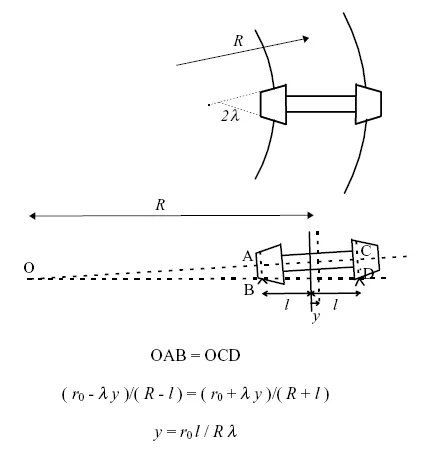
Figure 1.2 Redtenbacher’s formula for the rolling of a coned wheelset on a curve.
It can be seen, in broad terms, why the wheelset adopted its present form. If the flange is on the inside the conicity is positive and as the flange approaches the rail there will be a strong steering action tending to return the wheelset to the centre of the track. If the flange is on the outside the conicity is negative and the wheelset will simply run into the flange and remain in contact as the wheelset moves along the track. Another factor is the behaviour in sharp curves. If the flange is on the inside then the lateral force applied by the rail to the leading wheelset is applied to the outer wheel and will be combined with an enhanced vertical load. As explained later, this diminishes the risk of derailment. With outside flanges the lateral force applied by the rail applied to the inner wheel which has a reduced vertical load and thus the risk of derailment is increased. These factors can be easily demonstrated with the aid of model wheelsets [3].
Thus, it can be seen that for small displacements from the centre of straight or slightly curved track the primary mode of guidance is conicity and it is on sharper curves and switches and crossings that the flanges become the essential mode of guidance. Though this appears to be a modern view, in 1838 Brunel [4] wrote
The flanges are a necessary precaution but they ought never to touch the rail and therefore they cannot be said to keep the wheels on the rails. They ought not to come into action except to meet an accidental, lateral force. A railway with considerable curves might be travelled over with carriages at any velocity and with wheels without flanges. The wheels are made conical, the smaller circumference at the outer edge. The pair of wheels are fixed to the axle and thus if anything throws the wheels in the slightest degree to one side the wheel is immediately rolling on a larger circumference than the other and the tendency to roll back is introduced. The carriage is kept always in the middle of the track. A beautiful arrangement.
As a concept, this view led to many significant improvements in the design of railway vehicle suspensions in the 20th century.
Coning of the wheel tread was well established by 1821. George Stephenson in his Observations on Edge and Tram Railways [5] stated that
It must be understood the form of edge railway wheels are conical that is the outer is rather less than the inner diameter about 3/16 of an inch. Then from a small irregularity of the railway the wheels may be thrown a little to the right or a little to the left, when the former happens the right wheel will expose a larger and the left one a smaller diameter to the bearing surface of the rail which will cause the latter to loose ground of the former but at the same time in moving forward it gradually exposes a greater diameter to the rail while the right one on the contrary is gradually exposing a lesser which will cause it to loose ground of the left one but will regain it on its progress as has been described alternately gaining and loosing ground of each other which will cause the wheels to proceed in an oscillatory but easy motion on the rails.
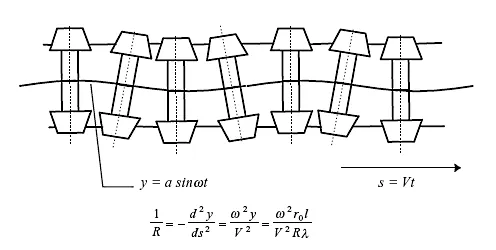
Figure 1.3 Derivation of Klingel’s formula for the kinematic oscillation of a wheelset from Redtenbacher’s formula in Figure 1.2.
This is a very clear description of what is now called the kinematic oscillation, as shown in Figure 1.3.
Thus, if a wheelset is rolling along the track and is displaced slightly to one side, the wheel on one side is running on a larger radius and the wheel on the other side is running on a smaller radius. Because the wheels are mounted on a common axle one wheel will move forward faster than the other because its instantaneous rolling radius is larger. Hence, if pure rolling is maintained, the wheelset moves back into the centre of the track – a steering action is provided by the coning. However, the wheelset overshoots the centre of the track and the result is the kinematic oscillation.
In 1883 Klingel gave the first mathematical analysis of the kinematic oscillation [6] and derived the relationship between the wavelength Λ and the wheelset conicity λ, wheel radius r0 and lateral distance between the contact points between wheels and rails 2l as
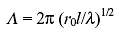
This simple formula follows purely from the geometry of Figure 1.3, and is consistent with Redtenbacher’s formula for the wheelset in a curve. Since distance along the track s = Vt where V is the for...
Table of contents
- Cover Page
- Title Page
- Copyright Page
- Arrangement of the book
- Preface
- 1: Basic Concepts
- 2: Equations of Motion
- 3: Dynamics of the Wheelset
- 4: Guidance of the Two-Axle Vehicle
- 5: Dynamic Stability of the Two-Axle Vehicle
- 6: The Bogie Vehicle
- 7: The Three-Axle Vehicle
- 8: Articulated Vehicles
- 9: Unsymmetric Vehicles
Frequently asked questions
Yes, you can cancel anytime from the Subscription tab in your account settings on the Perlego website. Your subscription will stay active until the end of your current billing period. Learn how to cancel your subscription
No, books cannot be downloaded as external files, such as PDFs, for use outside of Perlego. However, you can download books within the Perlego app for offline reading on mobile or tablet. Learn how to download books offline
Perlego offers two plans: Essential and Complete
- Essential is ideal for learners and professionals who enjoy exploring a wide range of subjects. Access the Essential Library with 800,000+ trusted titles and best-sellers across business, personal growth, and the humanities. Includes unlimited reading time and Standard Read Aloud voice.
- Complete: Perfect for advanced learners and researchers needing full, unrestricted access. Unlock 1.5M+ books across hundreds of subjects, including academic and specialized titles. The Complete Plan also includes advanced features like Premium Read Aloud and Research Assistant.
We are an online textbook subscription service, where you can get access to an entire online library for less than the price of a single book per month. With over 1.5 million books across 990+ topics, we’ve got you covered! Learn about our mission
Look out for the read-aloud symbol on your next book to see if you can listen to it. The read-aloud tool reads text aloud for you, highlighting the text as it is being read. You can pause it, speed it up and slow it down. Learn more about Read Aloud
Yes! You can use the Perlego app on both iOS and Android devices to read anytime, anywhere — even offline. Perfect for commutes or when you’re on the go.
Please note we cannot support devices running on iOS 13 and Android 7 or earlier. Learn more about using the app
Please note we cannot support devices running on iOS 13 and Android 7 or earlier. Learn more about using the app
Yes, you can access Fundamentals of Rail Vehicle Dynamics by Alan Wickens in PDF and/or ePUB format, as well as other popular books in Technology & Engineering & Civil Engineering. We have over 1.5 million books available in our catalogue for you to explore.