PIC16F1847 Microcontroller-Based Programmable Logic Controller
eBook - ePub

PIC16F1847 Microcontroller-Based Programmable Logic Controller

Advanced Concepts

Murat Uzam

Share book
  1. 456 pages
  2. English
  3. ePUB (mobile friendly)
  4. Available on iOS & Android
eBook - ePub

PIC16F1847 Microcontroller-Based Programmable Logic Controller

Advanced Concepts

Murat Uzam

Book details
Book preview
Table of contents
Citations

About This Book

The PIC16F1847-Based PLC project supports up to 4 analog inputs and 1 analog output, 1 High Speed Counter, 2 PWM (pulse width modulation) outputs, 1 Drum Sequencer Instruction with up to 16 steps, the implementation of Sequential Function Charts (SFCs) with up to 24 steps. This volume presents advanced concepts of the PIC16F1847-Based PLC project and consists of topics like program control, high speed counter and PWM macros. It further explains memory related drum sequencer instruction, sequential functional charts, and analog input and output modules. Aimed at researchers and graduate students in electrical engineering, power electronics, robotics and automation, sensors, this book:

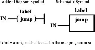
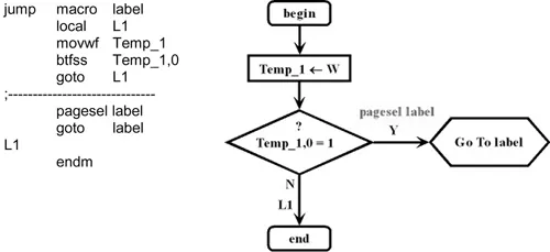
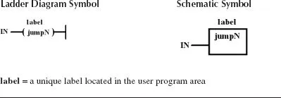
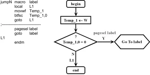
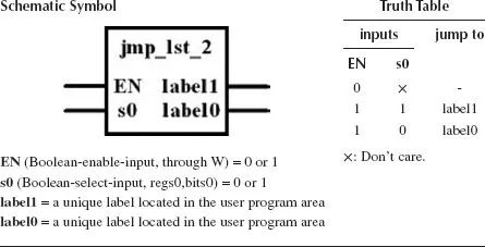
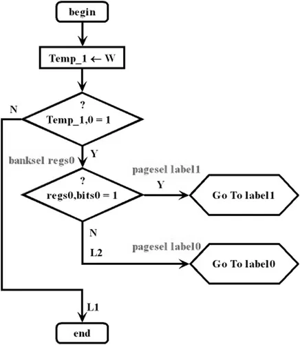
Presents program control macros to enable or disable a block of PLC program or to move execution of a program from one place to another.

Proposes a High-Speed Counter and four PWM Macros for high speed counting and PWM operations.

Develops memory related macros to enable the user to do memory read/write operations.

Provides a Drum Sequencer instruction with up to 16 steps and 16 outputs on each step.

Discusses the implementation of Sequential Function Chart (SFC) elements with up to 24 steps.

Frequently asked questions

How do I cancel my subscription?
Simply head over to the account section in settings and click on “Cancel Subscription” - it’s as simple as that. After you cancel, your membership will stay active for the remainder of the time you’ve paid for. Learn more here.
Can/how do I download books?
At the moment all of our mobile-responsive ePub books are available to download via the app. Most of our PDFs are also available to download and we're working on making the final remaining ones downloadable now. Learn more here.
What is the difference between the pricing plans?
Both plans give you full access to the library and all of Perlego’s features. The only differences are the price and subscription period: With the annual plan you’ll save around 30% compared to 12 months on the monthly plan.
What is Perlego?
We are an online textbook subscription service, where you can get access to an entire online library for less than the price of a single book per month. With over 1 million books across 1000+ topics, we’ve got you covered! Learn more here.
Do you support text-to-speech?
Look out for the read-aloud symbol on your next book to see if you can listen to it. The read-aloud tool reads text aloud for you, highlighting the text as it is being read. You can pause it, speed it up and slow it down. Learn more here.
Is PIC16F1847 Microcontroller-Based Programmable Logic Controller an online PDF/ePUB?
Yes, you can access PIC16F1847 Microcontroller-Based Programmable Logic Controller by Murat Uzam in PDF and/or ePUB format, as well as other popular books in Tecnología e ingeniería & Ingeniería eléctrica y telecomunicaciones. We have over one million books available in our catalogue for you to explore.

Information

1 Program Control Macros

Introduction

Program control macros (instructions) are used to enable or disable a block of PLC program or to move execution of a program from one place to another. These instructions allow the controller to efficiently perform special user-programmed routines that are executed only when required. This reduces the PLC scan time, thereby optimizing total system response. These instructions are generally used in pairs. When paired, the first instruction starts the flow control change, sending the PLC to a special routine of instructions in another section of the control program. The other instruction returns the PLC to the program it was running when the flow control change occurred.
In this chapter, the following program control macros are described for the PIC16F1847-Based PLC:
jump (jump to label),
jumpN (jump to label),
jmp_lst_2 (jump to one of two labels),
jmp_lst_4 (jump to one of four labels),
jmp_lst_8 (jump to one of eight labels),
call_SR (call subroutine),
return_SR (return from subroutine),
FOR (beginning of FOR-NEXT loop),
NEXT (end of FOR-NEXT loop),
clear_WDT (clear the watchdog timer).
In addition to these program control macros, the implementation of a master control relay (MCR) is also considered in this chapter.
The file “PICPLC_PIC16F1847_macros_Adv.inc”, which is downloadable from this book’s webpage under the downloads section, contains macros defined for the PIC16F1847-Based PLC explained in this book (Advanced Concepts). Let us now consider the program control macros in detail.

1.1 Jump Instructions

The jump instructions are used in a PLC program when it is desirable to jump over certain program rungs, upon the existence of certain condition(s). The area of the program to be jumped over is defined by the locations of the jump instructions and the specified label in the PLC program. Labels are located up on the left corner of the rung, right next to the power rail. When the jump instruction is executed, all PLC rungs between the jump instruction and the specified label are bypassed and the PLC continues scanning the very first rung after the label. Input conditions for the jumped rungs are not examined and outputs controlled by these rungs remain in their last state. Timers or counters located within the jump area stop functioning and do not update themselves during this period. Therefore, they are usually located outside the jumped section in the main program zone. Jump labels must be unique. Jumps can be forward/backward to a specified label. Jumps can be to the same label from more than one place in the PLC program. The label must be placed before the corresponding PLC rung. Both the jump instruction and the specified label must always be located within the same segment of code (either the user program, or in a subroutine).

1.2 Macro “jump” (Jump to Label)

Table 1.1 shows the symbols of the macro “jump”. Figure 1.1 depicts the macro “jump” and its flowchart. If there is power flow to a jump coil, as shown in the ladder diagram symbol, or if the jump box input is true, as shown in the schematic symbol, then program execution continues with the first rung following the specified label. A jump can be unconditional or conditional. In unconditional jumps, the jump instruction is connected to the power rail on the left side through the NO (normally open) contact of LOGIC1. In conditional jumps, the condition can be a Boolean variable or a combination of Boolean variables and comparisons. Assumption: The label can be in “user_program_1” or in “user_program_2” of Program memory.
TABLE 1.1:
The Symbols of the Macro “jump”
FIGURE 1.1: The macro “jump” and its flowchart.

1.3 Macro “jumpN” (Jump to Label)

Table 1.2 shows the symbols of the macro “jumpN”. Figure 1.2 depicts the macro “jumpN” and its flowchart. If there is no power flow to a jump coil (ladder diagram), or if the jump box input (schematic symbol) is false, then program execution continues with the first rung following the specified label. A “jumpN” can be unconditional or conditional. In unconditional jumps, the “jumpN” instruction is connected to the power rail on the left side through the NC (normally closed) contact of LOGIC1. In conditional jumps, the condition can be a Boolean variable or a combination of Boolean variables and comparisons. Assumption: The label can be in “user_program_1” or in “user_program_2” of Program memory.
TABLE 1.2:
The Symbols of the Macro “jumpN”
FIGURE 1.2: The macro “jumpN” and its flowchart.

1.4 Macro “jmp_lst_2” (Jump to One of Two Labels)

Table 1.3 shows the schematic symbol and the truth table of the macro “jmp_lst_2”. Figures 1.3 and 1.4 show the macro “jmp_lst_2” and its flowchart, respectively. The “jmp_lst_2” instruction acts as a program jump distributor to control the execution of program sections. Program execution continues with the program instructions that follow the destination jump label. Depending on the value of the select input s0, a jump occurs to one of the two selected program labels. The Boolean-enable-input signal EN should be loaded into W before this macro is invoked. When the enable input EN = 0, the instruction is not enabled and therefore no jump occurs. When the instruction is enabled, i.e., EN = 1, if s0 = 1 (or s0 = 0, respectively), then the jump occurs to label1 (or to label0, respectively). Assumption one: Labels can be in “user_program_1” or in “user_program_2” of Program memory. Assumption two: The operand “regs0,bits0” can be in any bank.
TABLE 1.3:
Schematic Symbol and Truth Table of the Macro “jmp_lst_2”
Images
FIGURE 1.3: The macro “jmp_lst_2”.
FIGURE 1.4: The flowchart of the macro “jmp_lst_2”.

1.5 Macro “jmp_lst_4” (Jump to One of Four Labels)

Table 1.4 shows the schematic symbol and the truth table of the macro “jmp_lst_4”. Figures 1.5 and 1.6 show the macro “jmp_lst_4” and its flowchart, respectively. The “jmp_lst_4” instruction acts as a program jump distributor to control the execution of program sections. Program execution continues with the program instructions that follow the destination jump label. Depending on the value of the select inputs s1 and s0, a jump occurs to one of the four selected program labels. The Boolean-enable-input signal EN should be loaded into W before this macro is invoked. When the enable input EN = 0, the instruction is not enabled and therefore no jump occurs. When the instruction is enabl...

Table of contents