- 336 pages
- English
- ePUB (mobile friendly)
- Available on iOS & Android
eBook - ePub
Radio and Electronics Cookbook
RSGB,
About this book
Radio and Electronics Cookbook is a unique collection of electronics projects, ideal for all electronics enthusiasts and experimenters. The simple step-by-step instructions also make this book ideal for amateurs seeking to build up their electronics skills and knowledge.
The projects draw on the massive enthusiasm and design know-how of the RSGB, the UK's leading federation of radio amateurs. Only a basic acquaintance with electronics construction is assumed, with clear step-by-step instructions and numerous illustrations supplied throughout. The projects are also supported with features on the electronics involved.
The circuits themselves provide a wealth of quick, rewarding construction projects ranging from radio receivers and amplifiers to test equipment, a moisture meter, a desk microphone, a water level alarm, and Christmas tree LEDs.
- A wealth of DIY and hobby projects
- Written by experts who really understand home electronics construction
- Includes factsheets to help you learn electronics basics as you work through the book
Trusted by 375,005 students
Access to over 1.5 million titles for a fair monthly price.
Study more efficiently using our study tools.
Information
1
A medium-wave receiver
Putting it together
Start by mounting the components on the terminal strip as shown in Figure 1, carefully checking the position and value of each one. The three capacitors are all the same, and so present no problem. They (and the resistors) may be connected either way round, unlike the two semiconductors (see later). The resistors are coded by means of coloured bands. You can refer to Chapter 7 if you have difficulty remembering the colours and their values.
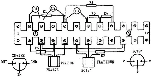
Figure 1 Terminal strip – position of components
| 1. Brown, Black, Yellow | 100 000 ohms | (R1, R5, R6) |
| 2. Green, Blue, Brown | 560 ohms | (R2) |
| 3. Red, Violet, Brown | 270 ohms | (R3) |
| 4. Brown, Black, Orange | 10 000 ohms | (R4) |
The integrated circuit (the ZN414Z) and the transistor (the BC184) must be connected correctly. Check Figure 1 carefully before fitting each device.
Now wind the coil. Most tubes are about 42 mm diameter and 110 mm long. Don’t worry if your tube is slightly different; it shouldn’t matter. Make two holes, about 3 mm apart, about 40 mm from one end, as shown in Figure 2. Loop your enamelled wire into one hole and out of the other, and draw about 100 mm through; loop this 100 mm through again, thus anchoring the wire firmly. Now wind on 80 turns, keeping the wire tight and the turns close together but not overlapping. After your 80th turn, make another two holes and anchor the wire in the same way as before. Again, leave about 100 mm free after anchoring. Using another piece of enamelled wire (with 100 mm ends as before), loop one end through the same two holes which contain the end anchor of the last winding, wind two turns and anchor the end of this short winding using another pair of holes. Figure 2 shows the layout.
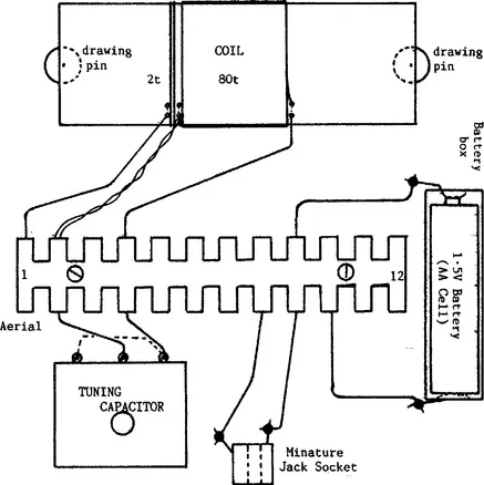
Figure 2 The layout of the parts on the wooden base
With some glass paper, remove the enamel from the ends of both pieces of wire which go through the same holes (i.e. the bottom of the large coil and the top of the small coil), then twist these bare ends together. Remove the enamel from the remaining ends of the coil. The coil is now finished!
The baseboard can be any piece of wood about 150 mm square. Fix the coil near the back edge using drawing pins and connect the wires from the coils to the terminal strip as shown in Figure 2. Using short pieces of PVC-insulated wire (and with assistance if you have never soldered before), solder one piece across the two outer tags of the variable capacitor, shown by the dotted line in Figure 2, and then two longer pieces to the centre tag and one outside tag. Connect these to the terminal strip. Then solder two more insulated wires on to the jack socket (into which you will plug your crystal earpiece), the other ends going to the terminal strip. The last two wires (one must be red) need to be soldered on to the battery box, their other ends going to the terminal strip also. Make sure the red wire goes to the positive terminal on the battery, and is connected to terminal 9. The other connection to the battery goes to terminal 10.
Attach the terminal strip t...
Table of contents
- Cover image
- Title page
- Table of Contents
- Copyright
- Preface
- Chapter 1: A medium-wave receiver
- Chapter 2: An audio-frequency amplifier
- Chapter 3: A medium-wave receiver using a ferrite-rod aerial
- Chapter 4: A simple electronic organ
- Chapter 5: Experiments with the NE555 timer
- Chapter 6: A simple metronome
- Chapter 7: What is a resistor?
- Chapter 8: Waves – Part 1
- Chapter 9: A beat-frequency oscillator
- Chapter 10: What is a capacitor?
- Chapter 11: Waves – Part 2
- Chapter 12: An LED flasher
- Chapter 13: Waves – Part 3
- Chapter 14: Choosing a switch
- Chapter 15: An aerial tuning unit for receiver
- Chapter 16: A simple 2 m receiver preamplifier
- Chapter 17: Receiving aerials for amateur radio
- Chapter 18: The Colt 80 m receiver – Part 1
- Chapter 19: A crystal radio receiver
- Chapter 20: The varactor (or varicap) diode
- Chapter 21: A portable radio for medium waves
- Chapter 22: The Colt 80 m receiver – Part 2
- Chapter 23: A simple transistor tester
- Chapter 24: An introduction to transmitters
- Chapter 25: The Colt 80 m receiver – Part 3
- Chapter 26: A two-way Morse practice system
- Chapter 27: The Colt 80 m receiver – Part 4
- Chapter 28: A simple crystal set
- Chapter 29: A crystal calibrator
- Chapter 30: A simple short-wave receiver – Part 1
- Chapter 31: A fruit-powered medium-wave radio
- Chapter 32: A capacitance bridge
- Chapter 33: A simple short-wave receiver – Part 2
- Chapter 34: A basic continuity tester
- Chapter 35: A charger for NiCad batteries
- Chapter 36: An 80 metre crystal-controlled CW transmitter
- Chapter 37: A solar-powered MW radio
- Chapter 38: A receiver for the 7 MHz amateur band
- Chapter 39: Diodes for protection
- Chapter 40: An RF signal probe
- Chapter 41: An RF changeover circuit
- Chapter 42: A low-light indicator
- Chapter 43: A J-pole aerial for 50 MHz
- Chapter 44: Measuring light intensity – the photometer
- Chapter 45: A 70 cm Quad loop aerial
- Chapter 46: A UHF field strength meter
- Chapter 47: Christmas tree LEDs
- Chapter 48: An audio signal injector
- Chapter 49: Standing waves
- Chapter 50: A standing-wave indicator for HF
- Chapter 51: A moisture meter
- Chapter 52: Simple aerials
- Chapter 53: A breadboard 80 m CW transmitter
- Chapter 54: A 7-element low-pass filter for transmitters
- Chapter 55: Radio-frequency mixing explained
- Chapter 56: A voltage monitor for a 12 V power supply
- Chapter 57: A 1750 Hz toneburst for repeater access
- Chapter 58: A circuit for flashing LEDs
- Chapter 59: Digital logic circuits
- Chapter 60: A resistive SWR indicator
- Chapter 61: An audio filter for CW
- Chapter 62: An electronic die
- Chapter 63: The absorption wavemeter
- Chapter 64: An HF absorption wavemeter
- Chapter 65: A vertical aerial for 70 cm
- Chapter 66: A UHF corner reflector aerial
- Chapter 67: A switched dummy load
- Chapter 68: A simple Morse oscillator
- Chapter 69: A bipolar transistor tester
- Chapter 70: The ‘Yearling’ 20 m receiver
- Chapter 71: Adding the 80 metre band to the Yearling receiver
- Chapter 72: How the Yearling works
- Chapter 73: A field strength meter
- Chapter 74: Preselector for a short-wave receiver
- Chapter 75: An audible continuity tester
- Chapter 76: An experimental 70 cm rhombic aerial
- Chapter 77: Water level alarm
- Chapter 78: A delta loop for 20 metres
- Chapter 79: A simple desk microphone
- Chapter 80: Morse oscillator
- Chapter 81: A simple 6 m beam
- Chapter 82: An integrated-circuit amplifier
- Chapter 83: A novice ATU
- Chapter 84: CW QRP transmitter for 80 metres
- Chapter 85: An audio booster for your hand-held
- Chapter 86: A grid dip oscillator
- Chapter 87: A CW transmitter for 160 to 20 metres
- Chapter 88: Matching the end-fed random-wire aerial
Frequently asked questions
Yes, you can cancel anytime from the Subscription tab in your account settings on the Perlego website. Your subscription will stay active until the end of your current billing period. Learn how to cancel your subscription
No, books cannot be downloaded as external files, such as PDFs, for use outside of Perlego. However, you can download books within the Perlego app for offline reading on mobile or tablet. Learn how to download books offline
Perlego offers two plans: Essential and Complete
- Essential is ideal for learners and professionals who enjoy exploring a wide range of subjects. Access the Essential Library with 800,000+ trusted titles and best-sellers across business, personal growth, and the humanities. Includes unlimited reading time and Standard Read Aloud voice.
- Complete: Perfect for advanced learners and researchers needing full, unrestricted access. Unlock 1.5M+ books across hundreds of subjects, including academic and specialized titles. The Complete Plan also includes advanced features like Premium Read Aloud and Research Assistant.
We are an online textbook subscription service, where you can get access to an entire online library for less than the price of a single book per month. With over 1.5 million books across 990+ topics, we’ve got you covered! Learn about our mission
Look out for the read-aloud symbol on your next book to see if you can listen to it. The read-aloud tool reads text aloud for you, highlighting the text as it is being read. You can pause it, speed it up and slow it down. Learn more about Read Aloud
Yes! You can use the Perlego app on both iOS and Android devices to read anytime, anywhere — even offline. Perfect for commutes or when you’re on the go.
Please note we cannot support devices running on iOS 13 and Android 7 or earlier. Learn more about using the app
Please note we cannot support devices running on iOS 13 and Android 7 or earlier. Learn more about using the app
Yes, you can access Radio and Electronics Cookbook by RSGB in PDF and/or ePUB format, as well as other popular books in Technology & Engineering & Industrial Design. We have over 1.5 million books available in our catalogue for you to explore.