- 416 pages
- English
- ePUB (mobile friendly)
- Available on iOS & Android
eBook - ePub
Principles of Transistor Circuits
About this book
Over the last 40 years, Principles of Transistor Circuits has provided students and practitioners with a text they can rely on to keep them at the forefront of transistor circuit design.
Although integrated circuits have widespread application, the role of discrete transistors both as important building blocks which students must understand, and as practical solutions to design problems, remains undiminished.
The ninth edition has been thoroughly updated to cover the latest technology and applications, including computer circuit simulation, and many diagrams have been revised to bring them in line with current usage. Updated topics include thyristors, Darlington transistors, amplifiers, ring modulators, power supplies, optoelectronics and logic circuits.
- The transistor circuits bible
- Updated with new developments in technology and applications
- Accessible step-by-step introduction ideal for noviceS
Trusted by 375,005 students
Access to over 1.5 million titles for a fair monthly price.
Study more efficiently using our study tools.
Information
Topic
DesignSubtopic
Industrial DesignChapter 1
Semiconductors and junction diodes
Introduction
The 1950s marked the beginning of a revolution in electronics. It started with the invention by William Shockley of the transistor, a minute three-terminal device which could switch, amplify and oscillate yet needed only a few microwatts of power; it was also robust and virtually everlasting. Inevitably the transistor replaced the electron tube (valve) in all except very high power applications.
The pace of the revolution was accelerated a decade later by the development of the integrated circuit or i.c. (popularly known as the silicon chip) in which transistors and other components are manufactured and interconnected by the planar process (see Appendix A) to form amplifiers, signal stores and other functional units on a single silicon slice. The miniaturisation now possible is such that several million transistors can be accommodated on an i.c. less than 1 cm2.
The applications of i.c.s seem boundless. They feature in activities as diverse as satellite communication and control of model railways. They are widely used in audio, video and radio equipment and they made possible the computers and microprocessors now universally employed in commerce and industry. Perhaps their most familiar applications are in digital watches, calculators and toys.
This book describes the properties of the various types of transistor and shows how they can be used in the design of electronic circuits. The principles described apply to circuits employing discrete transistors and those embodied in i.c.s. To explain the properties of transistors it is useful to begin with an account of the physics of semiconductors because all transistors, irrespective of type, depend on semiconducting material for their action.
Mechanism of semiconduction
As the name suggests a semiconducting material is one with a conductivity lying between that of an insulator and that of a conductor: that is to say one for which the resistivity lies between, say 1012 Ω-cm (a value typical of glass) and 10−6 Ω-cm (approximately the value for copper). Typical values for the resistivity of a semiconducting material lie between 1 and 100 Ω-cm.
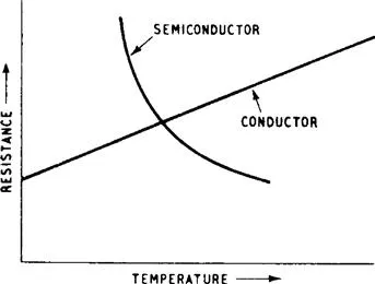
Such a value of resistivity could, of course, be obtained by mixing a conductor and an insulator in suitable proportions but the resulting material would not be a semiconductor. Another essential feature of a semiconducting material is that its electrical resistance decreases with increase in temperature over a particular temperature range which is characteristic of the semiconductor. This behaviour contrasts with that of elemental metallic conductors for which the resistance increases with rise in temperature. This is illustrated in Fig. 1.1, which gives curves for a conductor and a semiconductor. The resistance of the conductor increases linearly, whereas that of the semiconductor decreases exponentially, as temperature rises. Over the significant temperature range the relationship between resistance and temperature for a semiconductor could be written

where Rt is the resistance at an absolute temperature T, a and b are constants characteristic of the semiconductor material and e is the base of the natural logarithms, i.e. 2.81828 … The two curves in Fig. 1.1 are not to the same vertical scale of resistance.
All semiconducting materials exhibit the temperature dependence discussed in the paragraphs above in the pure state: the addition of impurities raises the temperature at which the material exhibits this behaviour, i.e. the region of negative temperature coefficient.
The element most widely used in transistor manufacture is silicon. It has largely replaced germanium which was also used in early transistors. When pure both elements have very poor conductivity and are of little direct use in transistor manufacture. But by the addition of a very small but controlled quantity of a particular type of impurity the conductivity can be increased and the material made suitable for use in transistors.
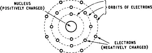
The behaviour of semiconductors can be explained in terms of atomic theory. The atom is assumed to have a central nucleus which carries most of the mass of the atom and has a positive charge. A number of electrons carrying a negative charge revolve around the nucleus. The total number of electrons revolving around a particular nucleus is sufficient to offset the positive nuclear charge, leaving the atom electrically neutral. The number of electrons associated with a given nucleus is equal to the atomic number of the element. The electrons revolve in a number of orbits and, for the purpose of this discussion, the orbits may be regarded as concentric, the nucleus being at the centre, as shown in Fig. 1.2. This diagram is greatly simplified; the orbits are in practice neither concentric nor co-planar.
The first orbit (sometimes called a ring or a shell) is complete when it contains 2 electrons, and an atom with a single complete shell is that of the inert gas, helium. The second ring is complete when it has 8 electrons, and the atom with the first 2 rings complete is that of the inert gas, neon. The third ring is stable when it has 8 or 18 electrons, and the atom having 2, 8 and 8 electrons in the 1st, 2nd and 3rd rings is that of the inert gas, argon. All the inert gases have their outermost shells stable. It is difficult to remove any electrons from a stable ring or to insert others into it. Atoms combine by virtue of the electrons in the outermost rings: for example an atom with one electron in the outermost ring will willingly combine with another whose outermost ring requires one electron for completion.
The inert gases, having their outer shells stable, cannot combine with other atoms or with each other. The number of electrons in the outermost ring or the number of electrons required to make the outermost ring complete has a bearing on the chemical valency of the element and the outermost ring is often called the valence ring.
Now consider the copper atom: it has 4 rings of electrons, the first 3 being complete and the 4th containing 1 electron, compared with the 32 needed for completion. Similarly the silver atom has 5 rings, 4 stable and the 5th also containing 1 out of 50 needed for completion. The atoms of both elements thus contain a single electron and this is loosely bound to the nucleus. It can be removed with little effort and is termed a free electron. A small e.m.f. applied to a collection of these atoms can set up a stream of free electrons, i.e. an electric current through the metal. Elements in which such free electrons are available are good electrical conductors.
It might be thought that an atom with 17 electrons in the outermost orbit would be an even better conductor, but this is not so. If one electron is added to such an orbit it becomes complete and a great effort is needed to remove it again.
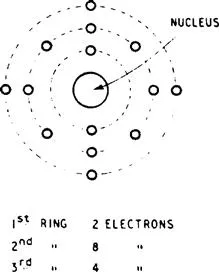
The arrangement of orbital electrons in a silicon atom is pictured in Fig. 1.3. There are three rings, the first containing 2 electrons, the second 8 and the third 4. The total number of electrons is 14, the atomic number of silicon. For comparison the germanium atom has four rings containing 2, 8, 18 and 4 electrons. These total 32, the atomic number for germanium. A significant feature of both atomic structures is that the outermost ring contains 4 electrons, a property of elements belonging to Group IV of the Periodic Table.
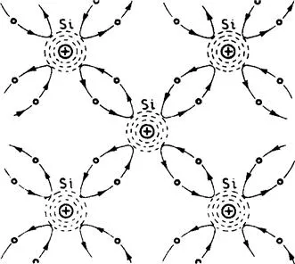
Covalent bonds
It might be thought that some of the 4 electrons in the valence ring of the silicon atom could easily be displaced and that these elements would therefore be good conductors. In fact, crystals of pure silicon are very poor conductors. To understand this we must consider the relationships between the valence electrons of neighbouring atoms when these are arranged in a regular geometric pattern as in a crystal. The valence electrons of each atom form bonds, termed covalent bonds, with those of neighbouring atoms as suggested in Fig. 1.4. It is difficult to portray a three-dimensional phenomenon in a two-dimensional diagram, but the diagram does show the valence electrons oscillating between two neighbouring atoms. The atoms behave in some respects as though each outer ring had 8 electrons and was stable. There are no free electrons and such a crystal is therefore an insulator: this is true of pure silicon at a very low temperature.
At room temperatures, however, silicon crystals do have a small conductivity even when they are as pure as modern chemical methods can make them. This is partly due to the presence of minute traces of impurities (the way in which these increase conductivity is explained later) and partly because thermal agitation enables some valence electrons to escape from their covalent bonds and thus become available as charge carriers. They are able to do this by virtue of their kinetic energy which, at normal temperatures, is sufficient to allow a very small number to break these bonds. If their kinetic energy is increased by the addition of light or by increase in temperature, more valence electrons escape and the conductivity increases. If the temperature is raised sufficiently conductivity becomes so great that it swamps semiconductor behaviour. This sets an upper limit to the temperature at which semiconductor devices can operate normally. For silicon devices the limit is sometimes quoted as 150°C.
Donor impurities
Suppose an atom of a Group-V element such as arsenic is introduced into a crystal of pure silicon. The atom enters into the lattice structure, taking the place of a si...
Table of contents
- Cover image
- Title page
- Table of Contents
- Copyright
- Preface to the ninth edition
- Chapter 1. Semiconductors and junction diodes
- Chapter 2. Basic principles of transistors
- Chapter 3. Common-base and common-gate amplifiers
- Chapter 4. Common-emitter and common-source amplifiers
- Chapter 5. Common-collector and common-drain amplifiers (emitter and source followers)
- Chapter 6. Bias and d.c. stabilisation
- Chapter 7. Small-signal a.f. amplifiers
- Chapter 8. Large-signal a.f. amplifiers
- Chapter 9. D.C. and pulse amplifiers
- Chapter 10. R.F. and I.F. amplifiers
- Chapter 11. Sinusoidal oscillators
- Chapter 12. Modulators, demodulators, mixers and receivers
- Chapter 13. Pulse generators
- Chapter 14. Sawtooth generators
- Chapter 15. Digital circuits
- Chapter 16. Further applications of transistors and other semiconductor devices
- Appendix A. The manufacture of transistors and integrated circuits
- Appendix B. Transistor parameters
- Appendix C. The stability of a transistor tuned amplifier
- Appendix D. Semiconductor letter symbols
- Index
Frequently asked questions
Yes, you can cancel anytime from the Subscription tab in your account settings on the Perlego website. Your subscription will stay active until the end of your current billing period. Learn how to cancel your subscription
No, books cannot be downloaded as external files, such as PDFs, for use outside of Perlego. However, you can download books within the Perlego app for offline reading on mobile or tablet. Learn how to download books offline
Perlego offers two plans: Essential and Complete
- Essential is ideal for learners and professionals who enjoy exploring a wide range of subjects. Access the Essential Library with 800,000+ trusted titles and best-sellers across business, personal growth, and the humanities. Includes unlimited reading time and Standard Read Aloud voice.
- Complete: Perfect for advanced learners and researchers needing full, unrestricted access. Unlock 1.5M+ books across hundreds of subjects, including academic and specialized titles. The Complete Plan also includes advanced features like Premium Read Aloud and Research Assistant.
We are an online textbook subscription service, where you can get access to an entire online library for less than the price of a single book per month. With over 1.5 million books across 990+ topics, we’ve got you covered! Learn about our mission
Look out for the read-aloud symbol on your next book to see if you can listen to it. The read-aloud tool reads text aloud for you, highlighting the text as it is being read. You can pause it, speed it up and slow it down. Learn more about Read Aloud
Yes! You can use the Perlego app on both iOS and Android devices to read anytime, anywhere — even offline. Perfect for commutes or when you’re on the go.
Please note we cannot support devices running on iOS 13 and Android 7 or earlier. Learn more about using the app
Please note we cannot support devices running on iOS 13 and Android 7 or earlier. Learn more about using the app
Yes, you can access Principles of Transistor Circuits by S W Amos,Mike James in PDF and/or ePUB format, as well as other popular books in Design & Industrial Design. We have over 1.5 million books available in our catalogue for you to explore.