eBook - ePub
Magnetic Bearings and Bearingless Drives
- 400 pages
- English
- ePUB (mobile friendly)
- Available on iOS & Android
eBook - ePub
Magnetic Bearings and Bearingless Drives
About this book
The application of bearingless drives is emerging as an important technique in the areas of high-speed machinery and motion-control, and this book aims to provide a thorough grounding in the principles behind this cutting-edge technology. Basic principles are described in detail with practical examples to aid understanding, and the different types of bearingless drives are introduced, along with coverage of test machines and applications.Aimed at practising electrical and mechanical engineers and advanced students, Magnetic Bearings and Bearingless Drives provides an essential guide to an area of engineering previously only fully covered by large numbers of academic papers.· Unique and comprehensive coverage of a cutting-edge subject for electrical and mechanical engineers · A reference text and survey for designers, manufacturers and users of high-speed motors, generators and electrical drive systems · Examines the basic principles behind magnetic bearings, with key technologies and applications illustrated through examples and case studies
Trusted by 375,005 students
Access to over 1.5 million titles for a fair monthly price.
Study more efficiently using our study tools.
Information
1
Introduction
Tadashi Fukao and Akira Chiba
In this chapter, an overview of bearingless drives and magnetic bearings is presented; the principle of radial force generation is discussed and a typical motor drive with magnetic bearings is introduced and compared with the bearingless drive. In addition, a definition of the bearingless motor is given and the related technologies and early developments are reviewed. Typical application structures, winding configurations, radial force and torque comparisons and applications are also included.
1.1 Magnetic bearing and motor drive
A new bearingless concept was introduced into ac drive technology in the late 1980s. Since then, the theory and background of the concept has been studied, with many test drives developed to gain experience of the operation and behaviour of a variety of bearingless ac drives.
Ac motor drive technology has been developed and applied in a wide range of applications since the 1970s because of their advantages over dc motor drives, such as high performance, compactness, lighter weight, use of low maintenance motors and lower motor cost. The increase in power and rotational speed of ac drives has widened the application area. One maintenance task that still remains with an ac drive is bearing lubrication and renewal. In some applications, bearing maintenance is still a significant problem. For example, the bearings can present a major problem in motor drive applications in outer space, and also in harsh environments with radiation and poisonous substances. In addition, lubrication oil cannot be used in high vacuum, ultra high and low temperature atmospheres and food and pharmacy processes. Hence motor drives with magnetic suspension can enlarge the possible application areas of motor drives.
Figure 1.1 shows the principles of rotor radial force generation in both the magnetic bearing and bearingless motors. A rotating shaft is surrounded by the stator core. The rotor and stator are magnetized with four poles in a north, south, north, south sequence. There are strong magnetic attractive forces under these magnetic poles between the rotor and the stator cores. For example, a magnetic force of 40 N is generated in 1 cm2 with an airgap flux density of 1 T. In Figure 1.1(a), these four magnetic poles have equal flux density and hence equal attractive force magnitudes. Thus, a vector sum of the four radial forces is zero. However, in Figure 1.1(b), one north pole is stronger than the other three poles so that the net attractive force is strong. Hence the unbalanced airgap flux density distribution results in radial magnetic force acting on the rotor. In this case, rotor radial force on the rotor is generated in the right-hand direction. In both radial magnetic bearing and bearingless motors, rotor radial force is generated by an unbalanced magnetic field; i.e., the rotor radial force is generated by the difference of radial forces between the magnetic poles. The attractive force is an inherently unstable force as it is stronger if the rotor moves in the force direction. The zero-radial-force point at the centre of the stator bore is an unstable point so that negative feedback is necessary.
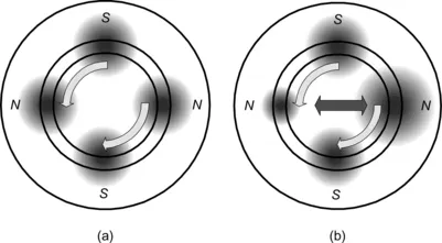
Figure 1.1 Radial force generation by unbalanced airgap flux density: (a) balanced airgap flux density; (b) unbalanced airgap flux density
In the Japanese Railways (JR) magnetically levitated train, the magnetic suspension force is generated by the interaction between the superconductor coil flux and an induced coil current. This means that a negative feedback controller is not required. In some flywheel applications, superconductor materials are used as magnetic bearings. These superconductor coils or materials provide stable magnetic suspension. However, the cost is quite high because a refrigerator and thermal insulation are required. These days, attractive magnetic force production requires simple, light-weight and cost-effective solutions for the magnetic suspension. Hence this book focuses on magnetic attractive forces.
Figure 1.2 shows the typical structure of a motor drive system equipped with magnetic bearings. The motor is located between the two radial magnetic bearings. Each radial magnetic bearing generates radial forces in two perpendicular radial axes. The radial forces are controlled by negative feedback control systems so that the radial shaft position is regulated to the centre of the stator bore. The left-hand magnetic bearing is regulated in two radial axis coordinates x1 and y1.
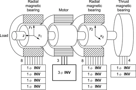
Figure 1.2 Motor with magnetic bearings
The right-hand radial magnetic bearing is regulated in radial axis coordinates x2 and y2. The thrust position on the z-axis, i.e., in the shaft direction, is regulated by axial forces generated by a thrust magnetic bearing. In total there are the five axes, x1, y1, x2, y2 and z, which are regulated by magnetic bearing systems.
Each radial magnetic bearing has four coils in a stator. Two coils are arranged on the x-axis and another two coils are on the y-axis. With a current in one coil, a magnetic attractive force is generated. A radial force in the x-axis direction is generated due to a difference in the magnetic attractive forces generated by the x-axis coils.
Coil currents in magnetic bearings are regulated by power-electronic circuits. In most cases, single-phase voltage-source inverters are utilized. A single-phase inverter can regulate one coil current so four single-phase inverters with eight output wires are necessary in a radial magnetic bearing.
In the thrust magnetic bearing, there are two coils so two single-phase inverters are connected to regulate the coil currents and generate radial force in axial direction.
The motor is responsible for generating torque around the shaft or z-axis. The rotational speed of the shaft is controlled by the motor torque and described by the torque equation of the system. A 3-phase inverter is connected to the motor terminals through three wires, with the motor windings connected in a wye or delta form (assuming 3-phase operation). The inverter supplies variable frequency and variable voltage based upon the shaft rotational speed and torque control requirements. The inverter frequency is proportional to the speed for most motors and the voltage/frequency ratio is usually almost constant up to the field weakening region.
1.2 Bearingless drives
Figure 1.3 shows the structure of a bearingless drive. Two bearingless units are constructed on a single shaft. Each bearingless unit generates radial forces as well as rotational torque. The left-hand bearingless unit is responsible for x1 and y1 radial positioning while the right-hand unit is responsible for x2 and y2 positioning. The total drive torque is twice the rated torque of the bearingless unit because the units share the torque production. Each bearingless unit has three terminals for the suspension windings and another three terminals for the motor windings. The respective motor phase windings of each unit are connected in series as shown in Figure 1.3 so that a wye connection is formed with two series-connected phase windings in each phase leg. It is important that the series-connected phase windings and rotor are correctly aligned in both units so that if the motor current lies on the rotor q-axis in one unit then it also lies on the rotor q-axis of the other. A single 3-phase inverter is connected to the series-connected motor windings and supplies variable ...
Table of contents
- Cover image
- Title page
- Table of Contents
- Copyright
- List of Contributors
- Foreword
- Preface
- Acknowledgements
- Chapter 1: Introduction
- Chapter 2: Electro-magnetics and mathematical model of magnetic bearings
- Chapter 3: Magnetic bearing controllers
- Chapter 4: Mechanical dynamics
- Chapter 5: Power electronic circuits for magnetic bearings
- Chapter 6: Primitive model and control strategy of bearingless motors
- Chapter 7: Analysis in rotational coordinates and magnetic suspension strategy for bearingless drives with 2-pole and 4-pole windings
- Chapter 8: Field orientation, VA requirement and magnetic saturation
- Chapter 9: Cylindrical permanent magnet synchronous bearingless motors
- Chapter 10: Inset types of permanent magnet bearingless motor
- Chapter 11: Buried permanent magnet bearingless motors
- Chapter 12: Synchronous reluctance bearingless motors
- Chapter 13: Bearingless induction motors
- Chapter 14: Homopolar, hybrid and consequent-pole bearingless motors
- Chapter 15: Switched reluctance bearingless motors
- Chapter 16: Winding arrangement variations
- Chapter 17: Mechanical structure and position regulation
- Chapter 18: Displacement sensors and sensorless operation
- Chapter 19: Controllers and power electronics
- Chapter 20: Design procedure and examples
- Chapter 21: Applications and test machines
- Index
Frequently asked questions
Yes, you can cancel anytime from the Subscription tab in your account settings on the Perlego website. Your subscription will stay active until the end of your current billing period. Learn how to cancel your subscription
No, books cannot be downloaded as external files, such as PDFs, for use outside of Perlego. However, you can download books within the Perlego app for offline reading on mobile or tablet. Learn how to download books offline
Perlego offers two plans: Essential and Complete
- Essential is ideal for learners and professionals who enjoy exploring a wide range of subjects. Access the Essential Library with 800,000+ trusted titles and best-sellers across business, personal growth, and the humanities. Includes unlimited reading time and Standard Read Aloud voice.
- Complete: Perfect for advanced learners and researchers needing full, unrestricted access. Unlock 1.5M+ books across hundreds of subjects, including academic and specialized titles. The Complete Plan also includes advanced features like Premium Read Aloud and Research Assistant.
We are an online textbook subscription service, where you can get access to an entire online library for less than the price of a single book per month. With over 1.5 million books across 990+ topics, we’ve got you covered! Learn about our mission
Look out for the read-aloud symbol on your next book to see if you can listen to it. The read-aloud tool reads text aloud for you, highlighting the text as it is being read. You can pause it, speed it up and slow it down. Learn more about Read Aloud
Yes! You can use the Perlego app on both iOS and Android devices to read anytime, anywhere — even offline. Perfect for commutes or when you’re on the go.
Please note we cannot support devices running on iOS 13 and Android 7 or earlier. Learn more about using the app
Please note we cannot support devices running on iOS 13 and Android 7 or earlier. Learn more about using the app
Yes, you can access Magnetic Bearings and Bearingless Drives by Akira Chiba,Tadashi Fukao,Osamu Ichikawa,Masahide Oshima,Masatugu Takemoto,David G Dorrell in PDF and/or ePUB format, as well as other popular books in Technology & Engineering & Mechanical Engineering. We have over 1.5 million books available in our catalogue for you to explore.