- 896 pages
- English
- ePUB (mobile friendly)
- Available on iOS & Android
eBook - ePub
Op Amp Applications Handbook
About this book
Operational amplifiers play a vital role in modern electronics design. The latest op amps have powerful new features, making them more suitable for use in many products requiring weak signal amplification, such as medical devices, communications technology, optical networks, and sensor interfacing. The Op Amp Applications Handbook may well be the ultimate op amp reference book available. This book is brimming with up-to-date application circuits, valuable design tips, and in-depth coverage of the latest techniques to simplify op amp circuit designs, and improve their performance. As an added bonus, a selection on the history of op amp development provides an extensive and expertly researched overview, of interest to anyone involved in this important area of electronics.* Seven major sections packed with technical information* Anything an engineer will want to know about designing with op amps can be found in this book* Op Amp Applications Handbook is a practical reference for a challenging engineering field.
Trusted by 375,005 students
Access to over 1.5 million titles for a fair monthly price.
Study more efficiently using our study tools.
Information
Subtopic
Industrial DesignChapter 1
Op Amp Basics
Introduction to Op Amp Basics
Within Chapter 1, discussions are focused on the basic aspects of op amps. After a brief introductory section, this begins with the fundamental topology differences between the two broadest classes of op amps, those using voltage feedback and current feedback. These two amplifier types are distinguished more by the nature of their internal circuit topologies than anything else. The voltage feedback op amp topology is the classic structure, having been used since the earliest vacuum tube based op amps of the 1940s and 1950s, through the first IC versions of the 1960s, and includes most op amp models produced today. The more recent IC variation of the current feedback amplifier has come into popularity in the mid-to-late 1980s, when higher speed IC op amps were developed. Factors distinguishing these two op amp types are discussed at some length.
Details of op amp input and output structures are also covered in this chapter, with emphasis on how such factors potentially impact application performance. In some senses, it is logical to categorize op amp types into performance and/or application classes, a process that works to some degree, but not altogether.
In practice, once past those obvious application distinctions such as “high speed” versus “precision,” or “single” versus “dual supply,” neat categorization breaks down. This is simply the way the analog world works. There is much crossover between various classes, i.e., a high speed op amp can be either single or dual-supply, or it may even fit as a precision type. A low power op amp may be precision, but it need not necessarily be single-supply, and so on. Other distinction categories could include the input stage type, such as FET input (further divided into JFET or MOS, which, in turn, are further divided into NFET or PFET and PMOS and NMOS, respectively), or bipolar (further divided into NPN or PNP). Then, all of these categories could be further described in terms of the type of input (or output) stage used.
So, it should be obvious that categories of op amps are like an infinite set of analog gray scales; they don’t always fit neatly into pigeonholes, and we shouldn’t expect them to. Nevertheless, it is still very useful to appreciate many of the aspects of op amp design that go into the various structures, as these differences directly influence the optimum op amp choice for an application. Thus structure differences are application drivers, since we choose an op amp to suit the nature of the application—for example, single-supply.
In this chapter various op amp performance specifications are also discussed, along with those specification differences that occur between the broad distinctions of voltage or current feedback topologies, as well as the more detailed context of individual structures. Obviously, op amp specifications are also application drivers; in fact, they are the most important since they will determine system performance. We choose the best op amp to fit the application, based on the required bias current, bandwidth, distortion, and so forth.
SECTION 1-1
Introduction
Walt Jung
As a precursor to more detailed sections following, this introductory chapter portion considers the most basic points of op amp operation. These initial discussions are oriented around the more fundamental levels of op amp applications. They include: Ideal Op Amp Attributes, Standard Op Amp Feedback Hookups, The Non-Ideal Op Amp, Op Amp Common-Mode Dynamic Range(s), the various Functionality Differences of Single and Dual-Supply Operation, and the Device Selection process.
Before op amp applications can be developed, some requirements are in order. These include an understanding of how the fundamental op amp operating modes differ, and whether dual-supply or single-supply device functionality better suits the system under consideration. Given this, then device selection can begin and an application developed.
First, an operational amplifier (hereafter simply op amp) is a differential input, single-ended output amplifier, as shown symbolically in Figure 1-1. This device is an amplifier intended for use with external feedback elements, where these elements determine the resultant function, or operation. This gives rise to the name “operational amplifier,” denoting an amplifier that, by virtue of different feedback hookups, can perform a variety of operations.1 At this point, note that there is no need for concern with any actual technology to implement the amplifier. Attention is focused more on the behavioral nature of this building block device.
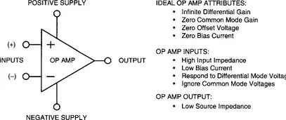
Figure 1-1 The ideal op amp and its attributes
An op amp processes small, differential mode signals appearing between its two inputs, developing a single-ended output signal referred to a power supply common terminal. Summaries of the various ideal op amp attributes are given in Figure 1-1. While real op amps will depart from these ideal attributes, it is very helpful for first-level understanding of op amp behavior to consider these features. Further, although these initial discussions talk in idealistic terms, they are also flavored by pointed mention of typical “real world” specifications—for a beginning perspective.
It is also worth noting that this op amp is shown with five terminals, a number that happens to be a minimum for real devices. While some single op amps may have more than five terminals (to support such functions as frequency compensation, for example), none will ever have fewer. By contrast, those elusive ideal op amps don’t require power, and symbolically function with just four pins.2
Ideal Op Amp Attributes
An ideal op amp has infinite gain for differential input signals. In practice, real devices will have quite high gain (also called open-loop gain) but this gain won’t necessarily be precisely known. In terms of spe...
Table of contents
- Cover image
- Title page
- Table of Contents
- Copyright
- Foreword
- Preface
- Acknowledgments
- Op Amp History Highlights
- Chapter 1: Op Amp Basics
- Chapter 2: Specialty Amplifiers
- Chapter 3: Using Op Amps with Data Converters
- Chapter 4: Sensor Signal Conditioning
- Chapter 5: Analog Filters
- Chapter 6: Signal Amplifiers
- Chapter 7: Hardware and Housekeeping Techniques
- Chapter 8: Op Amp History
- SUBJECT INDEX
- ANALOG DEVICES’ PARTS INDEX
- STANDARD DEVICE PARTS INDEX
Frequently asked questions
Yes, you can cancel anytime from the Subscription tab in your account settings on the Perlego website. Your subscription will stay active until the end of your current billing period. Learn how to cancel your subscription
No, books cannot be downloaded as external files, such as PDFs, for use outside of Perlego. However, you can download books within the Perlego app for offline reading on mobile or tablet. Learn how to download books offline
We are an online textbook subscription service, where you can get access to an entire online library for less than the price of a single book per month. With over 1.5 million books across 990+ topics, we’ve got you covered! Learn about our mission
Look out for the read-aloud symbol on your next book to see if you can listen to it. The read-aloud tool reads text aloud for you, highlighting the text as it is being read. You can pause it, speed it up and slow it down. Learn more about Read Aloud
Yes! You can use the Perlego app on both iOS and Android devices to read anytime, anywhere — even offline. Perfect for commutes or when you’re on the go.
Please note we cannot support devices running on iOS 13 and Android 7 or earlier. Learn more about using the app
Please note we cannot support devices running on iOS 13 and Android 7 or earlier. Learn more about using the app
Yes, you can access Op Amp Applications Handbook by Walt Jung in PDF and/or ePUB format, as well as other popular books in Technology & Engineering & Industrial Design. We have over 1.5 million books available in our catalogue for you to explore.