Modern Control of DC-Based Power Systems: A Problem-Based Approach addresses the future challenges of DC Grids in a problem-based context for practicing power engineers who are challenged with integrating DC grids in their existing architecture. This reference uses control theory to address the main concerns affecting these systems, things like generation capacity, limited maximum load demands and low installed inertia which are all set to increase as we move towards a full renewable model. Offering a new approach for a problem-based, practical approach, the book provides a coordinated view of the topic with MATLAB®, Simulink® files and additional ancillary material provided.
- Includes Simulink® Files (of examples and for lab training classes) and MATLAB® files
- Presents video slides to support the problem-based approach to understanding DC Power System control and application
- Provides stability analysis of DC networks and examples of common stability problems
Trusted by 375,005 students
Access to over 1.5 million titles for a fair monthly price.
Overview—Voltage Stabilization of Constant Power Loads
Abstract
Throughout this chapter the reader will be introduced to the characteristics of the Constant Power Load (CPL) while being connected to a DC bus in Section 1.1. The Sections 1.2–1.4 present an overview on the previous research activities performed for stabilizing CPLs. Section 1.5 offers a summary of this chapter.
Keywords
Constant Power Load; DC bus; converter; actuator
Throughout this chapter the reader will be introduced to the characteristics of the Constant Power Load (CPL) while being connected to a DC bus in Section 1.1. The Sections 1.2–1.4 present an overview on the previous research activities performed for stabilizing CPLs. Section 1.5 offers a summary of this chapter.
1.1 Constant Power Load Connected to a DC Bus
The interaction of electrical subsystems around a DC bus can lead to the instability of the latter. Often in these cases, it is associated with the occurrence of instability when CPLs are connected on the DC bus [1–14]. The phenomenon of instability is considered then as the consequence of the connection of a CPL on a DC bus.
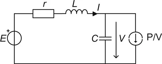
When there is an element present which regulates the power consumption of a load (e.g., inverter/actuator, converter/battery converter, drive), it is possible to assume the aforementioned CPL behavior. The control of the load will then set the load to compensate disturbances on the bus. The load does not take into account the electrical state of the network (including DC bus). Thus, it will be seen by the DC bus as a constant power consuming element as shown in Fig. 1.1. The output of the source converter is represented by the voltage source E, which is interfaced through a filter circuit consisting of the equivalent series resistor of the inductor r, inductor L and capacitor C with the nonlinear load, which is represented by a current source with the characteristic P/V, V denotes the voltage drop over the capacitor.
Figure 1.1 Electrical system containing a nonlinear load.
The current absorbed by CPL on the DC bus can be modeled as Eq. (1.1) where for a given operating point (
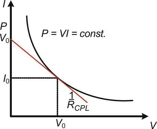
, the product of the load voltage and current is kept constant. The introduction of a CPL in the network implies the appearance of a nonlinearity of the
type. The characteristic current–voltage curve across the CPL is represented in Fig. 1.2.
(1.1)
(1.1)
Figure 1.2 Characteristic I–V curve of a Constant Power Load.
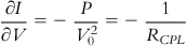
The rate of change of the current can be obtained by a linear approximation, deriving from Eq. (1.1) in the small area around the operating point. This yields the linear equivalent impedance RCPL at the given operating point Eq. (1.2).
(1.2)
(1.2)
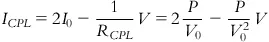
From Eq. (1.2) it can be observed that RCPL is dependent on the actual voltage and current. The curve representing the current versus voltage for a CPL in Eq. (1.3) can be approximated by a straight line that is tangent to the power curve at the operating point. The equation for this line is given as follows:
(1.3)
(1.3)
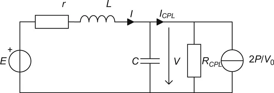
One can conclude that a CPL around its operating point has a behavior similar to that of a negative resistance in parallel with a constant current source. The diagram corresponding to the electrical behavior of the CPL around an operating point is depicted in Fig. 1.3. The output of the source converter is represented by the voltage source E, which is interfaced through a filter circuit consisting of the equivalent series resistor of the inductor r, the inductor L, and the capacitor C; where V denotes the voltage over the capacitor.
Figure 1.3 Electrical system containing a Constant Power Load, equivalent circuit around operating point.
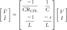
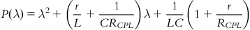
In order to have a mathematical observation of the effect of the CPL and RCPL on the network and to exclusively consider the variations of the system around the operating point lead toward omitting the DC component of Eq. (1.3), the resultant model is described in accordance to Eq. (1.4) and its characteristic polynomial is written in Eq. (1.5).
(1.4)
(1.4)
(1.5)
(1.5)
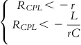
From the characteristic polynomial, one can deduce the relationship Eq. (1.6) which states the criteria for the eigenvalues of the system to have a negative real part. The first inequality holds because of the negative sign of
and usually the equivalent series resistor r is very small when comparing the absolute values, while the second will not always be respected since an increase in load power causes an increase in current which has as consequence an increase of
(which goes to 0).
(1.6)
(1.6)
Replacing
by this inequality the relationship (1.7) is obtained, which gives the local stability condition for the system.
(1.7)
(1.7)
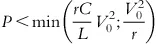
The relation
is less restrictive than the relationship
which ensures the existence of an operating point for the system while relation (1.8) gives the stability condition of the system operating points.
(1.8)
(1.8)
It is seen from Eq. (1.8) that a relationship between the stability of system, the sizing of the filter (r, L, C, and indirectly E) and the power consumed by the load can be expressed. It is seen that as the capacity of the inverter increases the system becomes more stable and vice versa for the inductance of the filter. In addition, these observations show that the negative resistance is used to excit...
Table of contents
Cover image
Title page
Table of Contents
Copyright
List of Figures
List of Tables
List of Contributors
List of Acronyms
Symbols Used in this Work
Preface
Introduction
Chapter One. Overview—Voltage Stabilization of Constant Power Loads
Chapter Two. Small-Signal Analysis of Cascaded Systems
Chapter Three. Background
Chapter Four. Generation Side Control
Chapter Five. Control Approaches for Parallel Source Converter Systems
Chapter Six. Simulation
Chapter Seven. Hardware In the Loop Implementation and Challenges
Index
Frequently asked questions
Yes, you can cancel anytime from the Subscription tab in your account settings on the Perlego website. Your subscription will stay active until the end of your current billing period. Learn how to cancel your subscription
No, books cannot be downloaded as external files, such as PDFs, for use outside of Perlego. However, you can download books within the Perlego app for offline reading on mobile or tablet. Learn how to download books offline
Perlego offers two plans: Essential and Complete
Essential is ideal for learners and professionals who enjoy exploring a wide range of subjects. Access the Essential Library with 800,000+ trusted titles and best-sellers across business, personal growth, and the humanities. Includes unlimited reading time and Standard Read Aloud voice.
Complete: Perfect for advanced learners and researchers needing full, unrestricted access. Unlock 1.5M+ books across hundreds of subjects, including academic and specialized titles. The Complete Plan also includes advanced features like Premium Read Aloud and Research Assistant.
Both plans are available with monthly, semester, or annual billing cycles.
We are an online textbook subscription service, where you can get access to an entire online library for less than the price of a single book per month. With over 1.5 million books across 990+ topics, we’ve got you covered! Learn about our mission
Look out for the read-aloud symbol on your next book to see if you can listen to it. The read-aloud tool reads text aloud for you, highlighting the text as it is being read. You can pause it, speed it up and slow it down. Learn more about Read Aloud
Yes! You can use the Perlego app on both iOS and Android devices to read anytime, anywhere — even offline. Perfect for commutes or when you’re on the go. Please note we cannot support devices running on iOS 13 and Android 7 or earlier. Learn more about using the app
Yes, you can access Modern Control of DC-Based Power Systems by Marco Cupelli,Antonino Riccobono,Markus Mirz,Mohsen Ferdowsi,Antonello Monti,marco Cupelli in PDF and/or ePUB format, as well as other popular books in Technology & Engineering & Electrical Engineering & Telecommunications. We have over 1.5 million books available in our catalogue for you to explore.