eBook - ePub
Offshore Pipelines
Design, Installation, and Maintenance
- 400 pages
- English
- ePUB (mobile friendly)
- Available on iOS & Android
eBook - ePub
Offshore Pipelines
Design, Installation, and Maintenance
About this book
The development of oil and gas fields offshore requires specialized pipeline equipment. The structures must be strong enough to with stand the harshest environments, and ensure that production is not interrupted and remains economically feasible. However, recent events in the Gulf of Mexico have placed a new importance on maintenance and reliability. A new section; Condition Based Maintenance (CBM), introduces the subject of maintenance, written by Tian Ran Lin, Queensland University of Technology, and Yong Sun, CSIRO Earth Science and Resource Engineering.
Two of the main objectives of CBM is maximizing reliability while preventing major or minor equipment malfunction and minimizing maintenance costs. In this new section, the authors deal with the multi-objective condition based maintenance optimization problem. CBM provides two major advantages: (1) an efficient approach for weighting maintenance objectives, and (2) a method for specifying physical methods for achieving those objectives. Maintenance cost and reliability objectives are calculated based on proportional hazards model and a control limit CBM replacement policy.
Written primarily for engineers and management personnel working on offshore and deepwater oil and gas pipelines, this book covers the fundamentals needed to design, Install, and commission pipeline projects. This new section along with a thorough update of the existing chapters represents a 30% increase in information over the previous edition.
- Covers offshore maintenance and maintenance support system
- Provides the fundamentals needed to design, Install, and commission pipeline project
- Methods and tools to deliver cost effective maintenance cost and system reliability
- New section on Condition-Based Maintenance written by Tian Ran Lin, Queensland University of Technology, and Yong Sun, CSIRO Earth Science and Resource Engineering ([email protected])
Trusted by 375,005 students
Access to over 1.5 million titles for a fair monthly price.
Study more efficiently using our study tools.
Information
Chapter 1
Introduction
Boyun Guo, Shanhong Song and Ali Ghalambor
1.1 Overview
The first pipeline was built in the United States in 1859 to transport crude oil (Wolbert, 1952). Through the one-and-a-half century of pipeline operating practice, the petroleum industry has proven that pipelines are by far the most economical means of large-scale overland transportation for crude oil, natural gas, and their products, clearly superior to rail and truck transportation over competing routes, given large quantities to be moved on a regular basis. Transporting petroleum fluids with pipelines is a continuous and reliable operation. Pipelines have demonstrated an ability to adapt to a wide variety of environments including remote areas and hostile environments. Because of their superior flexibility to the alternatives, with very minor exceptions, largely due to local peculiarities, most refineries are served by one or more pipelines.
Man’s inexorable demand for petroleum products intensified the search for oil in the offshore regions of the world as early as 1897, when the offshore oil exploration and production started from the Summerland, California (Leffler et al., 2003). The first offshore pipeline was born in the Summerland, an idyllic-sounding spot just southeast of Santa Barbara. Since then the offshore pipeline has become the unique means of efficiently transporting offshore fluids, i.e., oil, gas, and water.
Offshore pipelines can be classified as follows (Figure 1.1):
• Flowlines transporting oil and/or gas from satellite subsea wells to subsea manifolds;
• Flowlines transporting oil and/or gas from subsea manifolds to production facility platforms;
• Infield flowlines transporting oil and/or gas between production facility platforms;
• Export pipelines transporting oil and/or gas from production facility platforms to shore;
• Flowlines transporting water or chemicals from production facility platforms, through subsea injection manifolds, to injection wellheads.
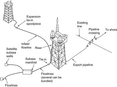
Figure 1.1 Uses of offshore pipelines.
Further downstream from the subsea wellhead, as more streams commingle, the diameter of the pipelines increases. Of course, the pipelines are sized to handle the expected pressure and fluid flow. To ensure desired flow rate of product, pipeline size varies significantly from project to project. To contain the pressures, wall thicknesses of the pipelines range from 3/8 in. to 1½ in.
1.2 Pipeline Design
Design of offshore pipelines is usually carried out in three stages: conceptual engineering, preliminary engineering, and detail engineering. During the conceptual engineering stage, issues of technical feasibility and constraints on the system design and construction are addressed. Potential difficulties are revealed and nonviable options are eliminated. Required information for the forthcoming design and construction are identified. The outcome of the conceptual engineering allows for scheduling of development and a rough estimate of associated cost. The preliminary engineering defines system concept (pipeline size and grade), prepares authority applications, and provides design details sufficient to order pipeline. In the detail engineering phase, the design is completed in sufficient detail to define the technical input for all procurement and construction tendering. The materials covered in this book fit mostly into the preliminary engineering stage.
A complete pipeline design includes pipeline sizing (diameter and wall thickness) and material grade selection based on analyses of stress, hydrodynamic stability, span, thermal insulation, corrosion and stability coating, and riser specification. The following data establish design basis:
• Reservoir performance
• Fluid and water compositions
• Fluid PVT properties
• Sand concentration
• Sand particle distribution
• Geotechnical survey data
• Meteorological and oceanographic data.
Table 1.1 shows sizes of some pipelines. It also gives order of magnitude of typical diameter/wall thickness ratios (D/t). Smaller diameter pipes are often flowlines with high design pressure leading to D/t between 15 and 20. For deepwater, transmission lines with D/t of 25–30 are more common. Depending upon types, some pipelines are bundled and others are thermal- or concrete-coated steel pipes to reduce heat loss and increase stability.
Table 1.1
Sample Pipeline Sizes
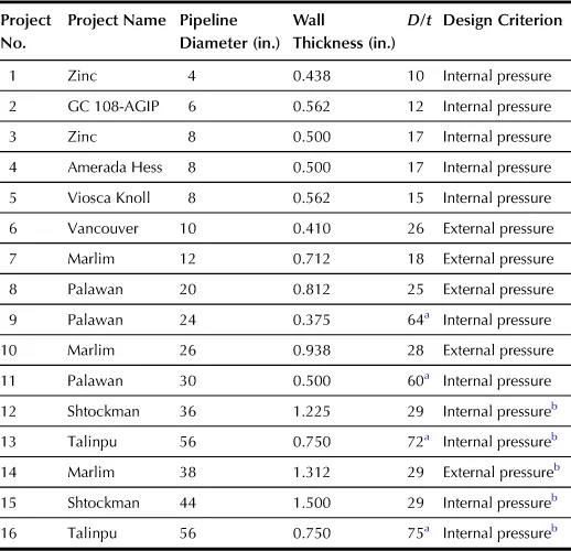
aPipelines with D/ t over 30.5 float in water without coating.
bBuckle arrestors required.
Although sophisticated engineering tools involving finite element simulations (Bai, 2001) are available to engineers for pipeline design, for procedure transparency, this book describes a simple and practical approach. Details are discussed in Part I of this book.
1.3 Pipeline Installation
Once the design is finalized, pipeline is ordered for pipe construction and coating and/or insulation fabrication. Upon shipping to the site, pipeline can be installed. There are several methods for pipeline installation including S-lay, J-lay, reel barge, and tow-in methods. As depicted in Figure 1.2, the S-lay requires a laying barge to have on its deck several welding stations where the crew welds together 40–80 ft of insulated pipe in a dry environment away from wind and rain. As the barge moves forward, the pipe is eased off the stern, curving downward through the water as it leaves until it reaches the touchdown point. After touchdown, as more pipe is played out, it assumes the normal S-shape. To reduce bending stress in the pipe, a stinger is used to support the pipe as it leaves the barge. To avoid buckling of the pipe, a tensioning roller and controlled forward thrust must be used to provide appropriate tensile load to the pipeline. This method is used for pipeline installations in a range of water depths from shallow to deep. The J-lay method is shown in Figure 1.3. It avoids some of the difficulties of S-laying such as tensile load and forward thrust. J-lay barges drop the pipe down almost vertically until it reaches touchdown. After that, the pipe assumes the normal J-shape. J-lay barges have a tall tower on the stern to weld and slip prewelded pipe sections of lengths up to 240 ft. With the simpler pipeline shape, J-lay can be used in deeper water than S-lay.
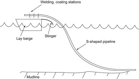
Figure 1.2 S-lay barge method for shallow to deep pipelines.
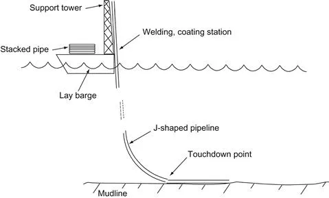
Figure 1.3 J-lay barge method for deepwater pipelines.
Small-diameter pipelines can be installed with reel barges where the pipe is welded, coated, and wound onshore to reduce costs. Horizontal reels lay pipe with an S-lay configuration. Vertical reels most commonly lay pipe by J-lay method but can also use S-laying.
There are four variations of the tow-in method: surface tow, mid-depth tow, off-bottom tow, and bottom tow. For the surface-tow approach, as shown in Figure 1.4, buoyancy modules are added to the pipeline so that it floats at the surface. Once the pipeline is towed on site by the two towboats, the buoyancy modules are removed or flooded, and the pipeline settles to the sea floor. Figure 1.5 illustrates the mid-depth tow. It requires fewer buoyancy modules. The pipeline settles to the bottom on its own when the forward progression ceases. Depicted in Figure 1.6 is the off-bottom tow. It involves both buoyancy modules and added weight in the form of chains. Once on location, the buoyancy is removed, and the pipeline settles to the sea floor. Figure 1.7 shows the bottom tow. The pipeline is allowed to sink to the bottom and then towed along the sea floor. It is primarily used for soft and flat sea floor in shallow water.
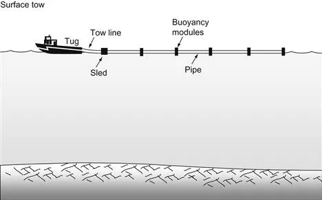
Figure 1.4 Surface tow for pipeline installation.
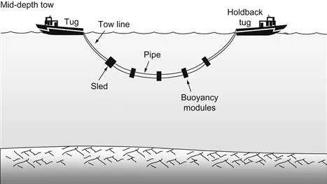
Figure 1.5 Mid-depth tow for pipeline installation.
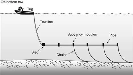
Figure 1.6 Off-bottom tow for pipeline installation.
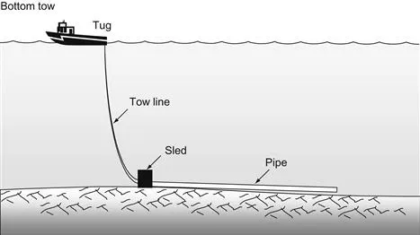
Figure 1.7 Bottom tow for pipeline installation.
Several concerns require attention during pipeline installation. These include pipeline external corrosion protection, pipeline installation protection, and installation bending stress/strain control. Details are discussed in Part II of this book.
1.4 Pipeline Operations
Pipeline operation starts with pipeline testing and commissioning. Operations to be carried out include flooding, cleaning, gauging, hydrostatic pressure testing, leak testing, and commissioning procedures. Daily operations include flow assurance and pigging operations to maintain the pipeline under good conditions.
Flow assurance is defined as an operation that generates a reliable flow of fluids from the reservoir to the sales point. The operation deals with formation and depositions of gas hydrates, paraffin, asphaltenes, and scales that can reduce flow efficiency of oil and gas pipelines. Because of technical challenges involved, this operation requires the combined efforts of a multidisciplinary team consisting of scientists, engineers, and field personnel.
Technical challenges in the flow assurance operation include prevention and control of depositions of gas hydrates, paraffin (wax), asphaltenes, and scales ...
Table of contents
- Cover image
- Title page
- Table of Contents
- Copyright
- Preface
- Chapter 1. Introduction
- Part I: Pipeline Design
- Part II: Pipeline Installation
- Part III: Pipeline Commissioning and Operations
- Part IV: Condition-Based Maintenance
- Appendix A. Gas–Liquid Multiphase Flow in Pipeline
- Appendix B. Steady and Transient Solutions for Pipeline Temperature
- Appendix C. Strength De-Rating of Old Pipelines
- Index
Frequently asked questions
Yes, you can cancel anytime from the Subscription tab in your account settings on the Perlego website. Your subscription will stay active until the end of your current billing period. Learn how to cancel your subscription
No, books cannot be downloaded as external files, such as PDFs, for use outside of Perlego. However, you can download books within the Perlego app for offline reading on mobile or tablet. Learn how to download books offline
Perlego offers two plans: Essential and Complete
- Essential is ideal for learners and professionals who enjoy exploring a wide range of subjects. Access the Essential Library with 800,000+ trusted titles and best-sellers across business, personal growth, and the humanities. Includes unlimited reading time and Standard Read Aloud voice.
- Complete: Perfect for advanced learners and researchers needing full, unrestricted access. Unlock 1.5M+ books across hundreds of subjects, including academic and specialized titles. The Complete Plan also includes advanced features like Premium Read Aloud and Research Assistant.
We are an online textbook subscription service, where you can get access to an entire online library for less than the price of a single book per month. With over 1.5 million books across 990+ topics, we’ve got you covered! Learn about our mission
Look out for the read-aloud symbol on your next book to see if you can listen to it. The read-aloud tool reads text aloud for you, highlighting the text as it is being read. You can pause it, speed it up and slow it down. Learn more about Read Aloud
Yes! You can use the Perlego app on both iOS and Android devices to read anytime, anywhere — even offline. Perfect for commutes or when you’re on the go.
Please note we cannot support devices running on iOS 13 and Android 7 or earlier. Learn more about using the app
Please note we cannot support devices running on iOS 13 and Android 7 or earlier. Learn more about using the app
Yes, you can access Offshore Pipelines by Boyun Guo,Shanhong Song Ph.D.,Ali Ghalambor,Tian Ran Lin PhD,Shanhong Song, Ph.D.,Ali Ghalambor, PhD,Tian Ran Lin, PhD in PDF and/or ePUB format, as well as other popular books in Technology & Engineering & Civil Engineering. We have over 1.5 million books available in our catalogue for you to explore.