- 240 pages
- English
- ePUB (mobile friendly)
- Available on iOS & Android
eBook - ePub
About this book
Tailor welded blanks are metallic sheets made from different strengths, materials, and/or thicknesses pre-welded together before forming into the final component geometry. By combining various sheets into a welded blank, engineers are able to 'tailor' the blank so that the properties are located precisely where they are needed and cost-effective, low weight components are produced. Tailor welded blanks for advanced manufacturing examines the manufacturing of tailor welded blanks and explores their current and potential future applications.Part one investigates processing and modelling issues in tailor welded blank manufacturing. Chapters discuss weld integrity, deformation during forming and the analytical and numerical simulation modelling of tailor welded blanks for advanced manufacturing. Part two looks at the current and potential future applications of tailor welded blanks. Chapters review tailor welded blanks of lightweight metals and of advanced high-strength steel and finally discuss the uses of tailor-welded blanks in the automotive and aerospace industries.With its distinguished editors and international team of expert contributors, Tailor welded blanks for advanced manufacturing proves an invaluable resource for metal fabricators, product designers, welders, welding companies, suppliers of welding machinery and anyone working in industries that use advanced materials such as in automotive and aerospace engineering. Engineers and academics involved in manufacturing and metallurgy may also find this book a useful reference.
- Examines the manufacturing of tailor welded blanks and explores their current and potential future applications
- Investigates processing and quality issues in tailor welded blank manufacturing including weld integrity and deformation
- Reviews both current and potential future applications of tailor welded blanks as well as specific applications in the automotive and aerospace industries
Trusted by 375,005 students
Access to over 1.5 million titles for a fair monthly price.
Study more efficiently using our study tools.
Information
Part I
Processing and modeling
1
Weld integrity of tailor welded blanks
M.M. Li, TWB Company, USA
Abstract:
The quality of a laser weld is sensitive to its geometrical integrity because of the small fusion zone, especially for those tailor welded blanks (TWBs) that are subject to post-weld forming. Most weld imperfections can be visualized from their appearance; however, not all of them are visible from the surface, such as porosity. Understanding the causes of weld imperfections helps the prevention of their creation. Nonetheless, knowing the characteristics of weld imperfections and their impact on the end application of the product allows the decision to be made regarding which weld imperfections are to be controlled or not. Proper weld monitoring systems and quality processes can be developed to control the quality of TWBs once the above factors, critical imperfections and their causes, are identified.
Key words
weld defect
laser welding
laser processing
concavity
pinhole
lack of penetration
lack of fusion
porosity
inclusion
mismatch
sporadic weld
laser triangulation
machine vision camera
camera vision
micro-structure
ultrasonic
eddy current
flux leakage
X-ray
1.1 Introduction
Tungsten inert gas (TIG), metal inert gas (MIG), electron beam and laser welding processes have been used for creating tailor welded blanks TWBs. However, due to the small heat-affected zone (HAZ) and fusion zone, the laser and electron beam welding processes produce less impact on the material properties than others. Laser welding has been the most frequently used process for producing TWBs due to the lower cost and greater flexibility compared to those of electron beam welding. For this reason, laser welding will be the focus of the material in this chapter.
Most weld imperfections are related to the weld geometry or chemical contents of the base materials. Improper fit-up between the two joining metal sheets is a major cause of imperfections related to weld geometry, such as concavity, mismatch and sporadic welds (i.e. a weld that does not have consistent weld geometry and is mostly a mixture of good weld and bad weld in short sections). Impurities or gaseous elements, such as oxygen, nitrogen and hydrogen, embedded in the material or introduced to the weld during the welding process can also create imperfections in the weld, such as porosity, pinholes or craters. The acceptance of a weld imperfection is normally determined by the application of the welded product. A pinhole or crater can be a defect for one product that undergoes a post-weld deep forming process and an accepted weld imperfection if no forming is required. Examples used in this chapter are based on a typical TWB joining two blanks of 1 mm and 2 mm in thickness.
Tests and measurement of weld integrity are divided into two categories, destructive and non-destructive. The most common destructive tests on TWBs are cross-sectioning, micro-hardness test, tensile test, bend test and formability test. These tests are used to understand the mechanical and metallurgical properties as well as the geometrical integrity of the weld. Destructive tests are normally time consuming. In some cases, fatigue tests are performed on welded parts that are subject to applications under cyclic loading. Non-destructive testing is desired for production part inspection, especially in mass production. Most non-destructive testing systems are designed to determine the geometrical integrity of the weld in the fusion zone. These systems are normally vision, ultrasound or electromagnetic based. When a non-destructive testing system is able to perform the inspection faster than the welding speed, such a system can then be used for real-time weld quality monitoring.
1.2 Typical weld imperfections
The most common imperfections seen in TWBs are discussed in this section. When the size of these imperfections becomes significant they are considered as defects for a part that requires a subsequent forming process performed on or around the weld seam. Splits inside or adjacent to the fusion zone can be found after the forming process if the weld imperfection is larger than the critical dimension. It is crucial to identify the imperfections of interest so that efforts can be focused on finding proper solutions to reducing and monitoring these imperfections. The critical dimension of imperfections is normally determined by the material grades and thickness. For example, for a low carbon steel weld with a gauge combination of 1 mm and 2 mm in its base materials, an imperfection with 0.5 mm in its largest linear dimension can be a defect if a post-weld forming process is required. The geometry of the imperfection is also an important factor in determining the critical dimension. Figure 1.1 shows a typical good weld cross-section with the thick gauge material on the left side and thin gauge material on the right side.
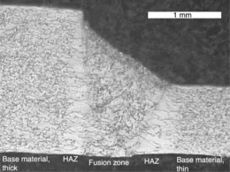
Figure 1.1 The cross-section of a typical good weld.
1.2.1 Pinhole and crater
A pinhole is formed during the welding process when part of the molten material is ejected away from the weld pool due to a burst of excess pressure in the keyhole or molten pool. When the laser beam hits a cluster of low temperature elements embedded in the base material or weld seam, due to the sudden increase of the pressure contributed by quick vaporization of the low temperature material, part of the molten material can be ejected away from the weld pool and forms a temporary cavity in the molten pool. A pinhole or crater is formed as a consequence of insufficient molten material filling into the cavity during the solidification process. The typical size of a pinhole is around 1.0 mm, while most pinholes have their largest dimension ranges from 0.5 mm to 2.0 mm. A crater is sometimes referred to as a partial pinhole or a blind pinhole. Additive materials such as aluminum, magnesium and zinc, which are popularly used in steel processing with vaporization temperatures far lower than that of steel, have a potential to vaporize rapidly and create a burst of pressure in the keyhole of a laser weld and result in a pinhole or crater, which is a partial pinhole. Figure 1.2 shows the top view of a pinhole. While breaking the pinhole along the welding direction, a cross-sectional view of the pinhole is illustrated in Fig. 1.3.
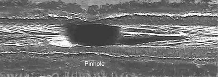
Figure 1.2 A pinhole located in a laser weld, tip view.

Figure 1.3 Cross-section of a pinhole (Fig. 1.2) along the welding direction.
Frequent cleaning of the welding equipment, especially the contact areas and the vicinity of the welding spot where fume and welding slag accumulate, may reduce the formation of pinholes. In addition, controlling incoming material to avoid unexpected inclusions and maintain weld edge cleanness also helps the reduction of pinhole formation. Most...
Table of contents
- Cover image
- Title page
- Table of Contents
- Copyright
- Contributor contact details
- Preface
- Part I: Processing and modeling
- Part II: Applications
- Index
Frequently asked questions
Yes, you can cancel anytime from the Subscription tab in your account settings on the Perlego website. Your subscription will stay active until the end of your current billing period. Learn how to cancel your subscription
No, books cannot be downloaded as external files, such as PDFs, for use outside of Perlego. However, you can download books within the Perlego app for offline reading on mobile or tablet. Learn how to download books offline
Perlego offers two plans: Essential and Complete
- Essential is ideal for learners and professionals who enjoy exploring a wide range of subjects. Access the Essential Library with 800,000+ trusted titles and best-sellers across business, personal growth, and the humanities. Includes unlimited reading time and Standard Read Aloud voice.
- Complete: Perfect for advanced learners and researchers needing full, unrestricted access. Unlock 1.5M+ books across hundreds of subjects, including academic and specialized titles. The Complete Plan also includes advanced features like Premium Read Aloud and Research Assistant.
We are an online textbook subscription service, where you can get access to an entire online library for less than the price of a single book per month. With over 1.5 million books across 990+ topics, we’ve got you covered! Learn about our mission
Look out for the read-aloud symbol on your next book to see if you can listen to it. The read-aloud tool reads text aloud for you, highlighting the text as it is being read. You can pause it, speed it up and slow it down. Learn more about Read Aloud
Yes! You can use the Perlego app on both iOS and Android devices to read anytime, anywhere — even offline. Perfect for commutes or when you’re on the go.
Please note we cannot support devices running on iOS 13 and Android 7 or earlier. Learn more about using the app
Please note we cannot support devices running on iOS 13 and Android 7 or earlier. Learn more about using the app
Yes, you can access Tailor Welded Blanks for Advanced Manufacturing by B Kinsey,X Wu in PDF and/or ePUB format, as well as other popular books in Technology & Engineering & Industrial Engineering. We have over 1.5 million books available in our catalogue for you to explore.