- 352 pages
- English
- ePUB (mobile friendly)
- Available on iOS & Android
eBook - ePub
Hydrostatic, Aerostatic and Hybrid Bearing Design
About this book
Solve your bearing design problems with step-by-step procedures and hard-won performance data from a leading expert and consultant
Compiled for ease of use in practical design scenarios, Hydrostatic, Aerostatic and Hybrid Bearing Design provides the basic principles, design procedures and data you need to create the right bearing solution for your requirements.
In this valuable reference and design companion, author and expert W. Brian Rowe shares the hard-won lessons and figures from a lifetime's research and consultancy experience. Coverage includes:
- Clear explanation of background theory such as factors governing pressure, flow and forces, followed by worked examples that allow you to check your knowledge and understanding
- Easy-to-follow design procedures that provide step-by-step blueprints for solving your own design problems
- Information on a wide selection of bearing shapes, offering a range and depth of bearing coverage not found elsewhere
- Critical data on optimum performance from load and film stiffness data to pressure ratio considerations
- Operating safeguards you need to keep in mind to prevent hot-spots and cavitation effects, helping your bearing design to withstand the demands of its intended application
Aimed at both experienced designers and those new to bearing design, Hydrostatic, Aerostatic and Hybrid Bearing Design provides engineers, tribologists and students with a one-stop source of inspiration, information and critical considerations for bearing design success.
- Structured, easy to follow design procedures put theory into practice and provide step-by-step blueprints for solving your own design problems.
- Covers a wide selection of bearing shapes, offering a range and depth of information on hydrostatic, hybrid and aerostatic bearings not found elsewhere.
- Includes critical data on optimum performance, with design specifics from load and film stiffness data to pressure ratio considerations that are essential to make your design a success.
Trusted by 375,005 students
Access to over 1.5 million titles for a fair monthly price.
Study more efficiently using our study tools.
Information
Chapter 1
Application
1.1 Introduction
Hydrostatic and aerostatic bearings have a great attraction to the engineer because machine parts supported on such bearings move with incomparable smoothness. This apparent perfection of motion derives from the complete separation of the solid sliding surfaces with a fluid film. At no point do the solid surfaces make any physical contact. This means to say the thin fluid film separating the surfaces is always larger than the height of any surface irregularities and as a result there is a complete absence of sticking friction. A mass supported on a hydrostatic or aerostatic bearing will silently glide down the smallest incline, an effect which is most striking with very large machines.
The hydrostatic bearing appears to have been invented by Girard (1852), who employed high-pressure water-fed bearings for a system of railway propulsion. Since that date there have been hundreds of patents and publications dealing with different designs and incorporating novel features. While some of these designs are potentially useful, many others introduce complexity rather than simplicity and are destined to remain in the archives. This text concentrates on configurations attractive for effectiveness and simplicity.
Aerostatic bearings employ pressurized air or gas whereas hydrostatic bearings employ a liquid lubricant. Aerostatic bearings offer some advantages but compressibility of gas imposes limitations in design layout compared with hydrostatic bearings. This book unifies the analysis of aerostatic and hydrostatic bearings, thus simplifying the design process and making it possible for the designer to achieve a wider range of designs.
Gauge Pressure and Absolute Pressure Conventions
The following convention is adopted throughout the book: The upper case letter P always refers to gauge pressure—that is, the excess of pressure above ambient pressure as measured on a typical pressure gauge:

The lower case letter p refers to absolute pressures—that is, the excess of pressure above absolute zero.
1.2 What are Hydrostatic, Hybrid, and Aerostatic Bearings?
The Hydrostatic or Aerostatic Principle
In a hydrostatic or aerostatic bearing the surfaces are separated by a film of fluid forced between the surfaces under pressure. The pressure is generated by an external pump. Hence a more general term “externally pressurized bearing” is often used. However, the separate terms “hydrostatic” and “aerostatic” are used here to maintain a clear distinction and allow differences to be made clear. An advantage of both types of bearing is that a complete lubricant film is maintained whenever the bearing is pressurized, even at zero speed.
Hydrostatic bearings should not be confused with hydrodynamic bearings, where although pressure is employed, the pressure does not support the applied load.
Hydrostatic and aerostatic circular pad bearings, with orifice flow control, are shown in Figure 1.1. Lubricant at a constant supply pressure Ps is pumped towards the bearing. The pressurized lubricant first passes through the orifice where dissipation of pressure energy causes reduced pressure on entry into the recess of the bearing pad. The recess is relatively deep compared with the bearing film thickness so that it offers little resistance to flow. Pressure in the recess is therefore constant throughout the recess volume. The flow passing through the recess leaves through the thin gap between the bearing land and the opposing surface. The pressure in the bearing film reduces as it passes across the bearing land and reaches atmospheric or ambient pressure at the exit. Other types of flow-control device can also be employed, such as the laminar flow group including capillary and slot restrictors.
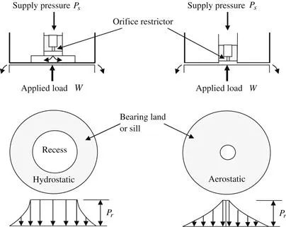
Figure 1.1 Circular Hydrostatic and Aerostatic Pads with Orifice Flow Control.
The film pressures oppose the applied load and maintain the separation of the surfaces. Recess pressure must be lower than supply pressure to allow for load variations. This is because the recess pressure must be able to vary with applied load. The principle can be demonstrated by two extreme cases. In the first case, a high applied load forces the bearing surfaces together and prevents flow out of the bearing. The flow rate through the orifice decreases to zero. Recess pressure therefore rises until it equals supply pressure. The second extreme is when load is reduced to zero. In this case the bearing gap will become very large so that the only resistance to flow is that offered by the orifice restrictor. This causes the flow to increase until the pressure drop across the orifice is sufficient to reduce the recess pressure to ambient pressure. The permissible range of applied loads must be such that the film thickness remains between the two extremes.
The load supported is calculated from the pressures in the bearing. Figure 1.2 shows two examples of hydrostatic pressures based on a simplified longitudinal flow assumption. The flow restrictors shown are assumed to be slots that reduce the inlet pressures Pi to a value equal to ½Ps. The bearing film force is therefore W = ¼PsLB. In the second example, a recess allows the inlet pressure Pi to spread uniformly throughout the recess. For a recess of length b and width B, the contribution from the recess to the load is PibB. The total load support includes the contribution due to the triangular distribution on the lands of length l. Each of these lands contributes a load support of ½PilB. The total bearing film force or load support is therefore W = PilB + PibB = ½PslB + ½PsbB. The principle for aerostatic bearings is similar.
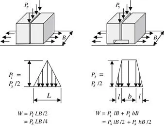
Figure 1.2 Examples of Hydrostatic Load and Pressure in One-Dimensional Longitudinal Flow.
The distinction between typical hydrostatic and hydrodynamic bearings is illustrated in Figure 1.3. In the hydrostatic example, lubricant enters four recesses through separate entry ports. When the shaft is concentric, pressures are almost constant around the shaft. Restrictors in the supply lines to each recess allow pressures to vary when the shaft is not concentric.
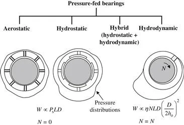
Figure 1.3 Aerostatic, Hydrostatic, Hydrodynamic, and Hybrid Journal Bearings.
The concentric value of recess pressure, at zero load, is usually half the supply pressure, that is Pro = Ps/2. If the bearing gap on one side is reduced, the bearing gap on the other side of the bearing is increased. Flow through the smaller gap is reduced and recess pressure rises. If the shaft is completely displaced to one side of the bearing, the recess pressure is almost equal to the supply pressure. On the opposite side, flow is increased and recess pressure drops. The reduction in pressures on one side is accompanied by an increase on the other. Thus, both sides of the bearing contribute force to withstand the externally applied force on the shaft. The main load parameters are supply pressure and bearing area.
W is proportional to PsLD for hydrostatic and aerostatic load support.
Two main configurations for hydrostatic, aerostatic, and hybrid journal bearings are illustrated in Figures 1.4 and 1.5. The recessed bearing is suitable for hydrostatic operation. Large recesses reduce friction area and power consumption at speed. Plain slot-entry and hole-entry bearings are suitable for all three modes of operation. Plain bearings minimize gas volume in an aerostatic bearing and hence reduce the effects of compressibility. Plain bearings maximize hydrodynamic support in hybrid bearings.
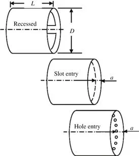
Figure 1.4 Recessed and Plain Journal Bearings.
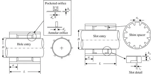
Figure 1.5 Typical Hole-Entry and Slot-Entry Hydrostatic, Aerostatic, and Hybrid Bearings.
Slot-entry aerostatic bearings can be designed with a reasonable degree of certainty. In contrast, orifice-fed aerostatic bearings introduce a degree of uncertainty due to: (1) dispersion losses and (2) the possibility of pneumatic hammer instability. It is always good practice to test a prototype bearing to ensure that the design requirements have been met.
The Hydrodynamic Principle
The hydrodynamic bearing illustrated in Figure 1.3 is said to be “self-acting” because the hydrodynamic pressures are generated by movement of the bearing surfaces. The moving surface drags lubricant by means of viscous forces into the converging gap. The converging gap region occurs on one-half of the bearing between the maximum gap on one side and the minimum gap on the other. The result is pressure in the converging region. The resulting bearing film force is equal and opposite to the applied force on the shaft. Hydrodynamic load support is...
Table of contents
- Cover Image
- Table of Contents
- Title
- Copyright
- Preface
- Usual Meaning of Symbols
- Chapter 1. Application
- Chapter 2. Basic Flow Theory
- Chapter 3. Power, Temperature Rise, and Shape Optimization
- Chapter 4. Pads
- Chapter 5. Flow Control and Restrictors
- Chapter 6. Basis of Design Procedures
- Chapter 7. Plane Hydrostatic and Aerostatic Bearings
- Chapter 8. Partial Journal Bearings
- Chapter 9. Recessed Hydrostatic Journal Bearings
- Chapter 10. Plain Journal Bearings
- Chapter 11. The Yates Bearing
- Chapter 12. Conical Journal Bearings
- Chapter 13. Spherical Bearings
- Chapter 14. Dynamics
- Chapter 15. Experimental Methods and Testing
- Index
Frequently asked questions
Yes, you can cancel anytime from the Subscription tab in your account settings on the Perlego website. Your subscription will stay active until the end of your current billing period. Learn how to cancel your subscription
No, books cannot be downloaded as external files, such as PDFs, for use outside of Perlego. However, you can download books within the Perlego app for offline reading on mobile or tablet. Learn how to download books offline
Perlego offers two plans: Essential and Complete
- Essential is ideal for learners and professionals who enjoy exploring a wide range of subjects. Access the Essential Library with 800,000+ trusted titles and best-sellers across business, personal growth, and the humanities. Includes unlimited reading time and Standard Read Aloud voice.
- Complete: Perfect for advanced learners and researchers needing full, unrestricted access. Unlock 1.5M+ books across hundreds of subjects, including academic and specialized titles. The Complete Plan also includes advanced features like Premium Read Aloud and Research Assistant.
We are an online textbook subscription service, where you can get access to an entire online library for less than the price of a single book per month. With over 1.5 million books across 990+ topics, we’ve got you covered! Learn about our mission
Look out for the read-aloud symbol on your next book to see if you can listen to it. The read-aloud tool reads text aloud for you, highlighting the text as it is being read. You can pause it, speed it up and slow it down. Learn more about Read Aloud
Yes! You can use the Perlego app on both iOS and Android devices to read anytime, anywhere — even offline. Perfect for commutes or when you’re on the go.
Please note we cannot support devices running on iOS 13 and Android 7 or earlier. Learn more about using the app
Please note we cannot support devices running on iOS 13 and Android 7 or earlier. Learn more about using the app
Yes, you can access Hydrostatic, Aerostatic and Hybrid Bearing Design by W. Brian Rowe in PDF and/or ePUB format, as well as other popular books in Technology & Engineering & Fluid Mechanics. We have over 1.5 million books available in our catalogue for you to explore.