- 72 pages
- English
- ePUB (mobile friendly)
- Available on iOS & Android
eBook - ePub
Welding Symbols On Drawings
About this book
Weld symbols on drawings was originally published in 1982 based on BS 499 (British Standards Institution 1980), ISO 2553 (International Standards Organisation 1979) and ANSI/AWS A2.4 (American Welding Society-1979) standards. These standards have been through numerous revisions over the last few years; and the current standards are ISO 2553 1992, BSEN 22553 1995, and ANSI/AWS A2.4 1998. The American system of symbolisation is currently used by approximately half of the world's industry. Most of the rest of the world use ISO. The British system was standardised in 1933 and the latest of five revisions was published in 1995 as BSEN 22553, which is identical to ISO 2553. For many years an ISO committee has been working on combining ISO and AWS to create a combined worldwide standard, but while discussions continue this could take many years to achieve.This contemporary book provides an up-to-date review on the application of ISO and AWS standards and a comparison between them. Many thousands of engineering drawings are currently in use, which have symbols and methods of representation from superseded standards. The current European and ISO standards and the American standard are substantially similar, but the ANSI/AWS standard includes some additional symbols and also symbols for non-destructive testing. Although symbols in the different standards are similar, the arrows showing locations of welds are different, these important differences are explained. ISO contains limited information on brazed or soldered joints these are covered in ANSI/AWS. Some examples of the application of welding symbols are also included.
- Important differences of welding symbols for different standards are explained
- Provides up to date information on the ISO and AWS standards and their comparison
- Contains examples of the application of welded symbols
Trusted by 375,005 students
Access to over 1.5 million titles for a fair monthly price.
Study more efficiently using our study tools.
Information
1
The need to specify welds
It is sometimes argued that it is unnecessary to specify welds on drawings and that the welder should be relied upon to deposit a suitable weld. This practice can be extremely risky because the type and size of the weld must be appropriate for the parent material and service conditions of the fabrication, and the necessary information and data are normally available only in the design office.
Figure 1.1 illustrates (a) the instruction ‘weld here’ and (b–d) three ways to follow this instruction.
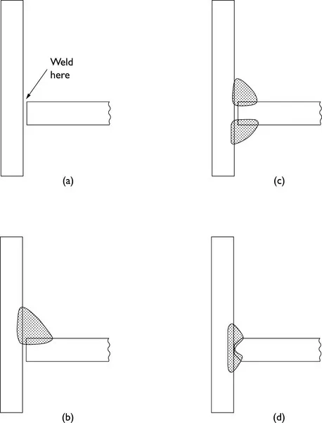
1.1 (a) The instruction ‘weld here’ and (b–d) three ways to follow this instruction.
The instruction ‘weld here’, illustrated in Fig. 1.1(a), is rarely seen on a drawing because it is open to a number of different interpretations as shown in Fig. 1.1(b), (c) and (d).
Figure 1.1(b) shows a single fillet weld. This weld is simple and therefore cheap to apply but could be seriously deficient in performance.
Figure 1.1(c) shows a double fillet weld, which takes longer to apply. Unless access is available to both sides of the joint, it will be impossible to weld it.
Figure 1.1(d) illustrates a T-butt/groove weld. This weld normally requires edge preparation on a horizontal member, and therefore is more complex and expensive. However, it may be essential for certain service conditions.
It can be seen from the previous examples that major problems will arise unless welded joints are carefully specified by the design office. The situation is particularly critical where, for example, work is placed with a subcontractor and the instructions need to be especially precise.
2
The advantages of symbols
When it is required to indicate a weld on a drawing, it may seem that the weld can simply be drawn as it will appear. In the majority of cases, symbolic representation can be used to cut down the time needed to complete the drawing and improve clarity.
To save time in drawing the edge preparation for a butt/groove weld or the shape and size of a fillet weld, a set of weld symbols can be used. These symbols are placed on a horizontal reference line. This line is attached to an arrow line which points to the location of the weld (see Fig. 2.1). In the ISO system there are two parallel reference lines, one solid and one dashed. In the AWS system a solid reference line is used.

2.1 ISO and AWS reference lines and arrow lines.
Apart from weld symbols placed on the reference line, additional information can be supplied adjacent to the tail which is generally omitted when not required.
The arrow line can point in any direction as shown in Fig. 2.2. This is so that it can locate welds in any welding position, for example flat or overhead. The arrow line is never drawn horizontally because this would make it appear to be a continuation of the reference line, which is always horizontal.
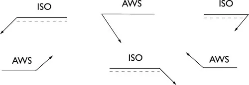
2.2 Possible directions in which arrow lines may point.
It is conventional practice to refer to the opposite sides of a welded joint as the arrow side and the other side (see Fig. 2.3).
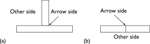
2.3 The arrow side and other side of a T-joint (a) and a butt/groove joint (b).
In the ISO system a weld on the arrow side is indicated by placing the weld symbol on the solid reference line and a weld on the other side has the symbol on the dashed line, as shown in Fig. 2.4.

2.4 Sy mbolisation of a weld on the arrow side and a weld on the other side in the ISO and AWS systems.
In the AWS system the weld symbol for a weld on the arrow side is placed below the line and for a weld on the other side the symbol is placed above the line.
In the ISO system the dashed line can be drawn above or below the solid line but the symbols on the solid line always refer to the arrow side of the joint. Symbols on the dashed line indicate a weld on the other side. It is recommended that the solid line is always drawn above the dashed line as standard practice. If a weld is made on both sides, as in a double fillet weld, the weld symbol is placed on both sides of the reference line or lines, in which case, in the ISO system, the dashed line can be omitted.
Figure 2.5 (a–f) shows the use of symbols to indicate the type and size of a T-butt weld and a double fillet weld.
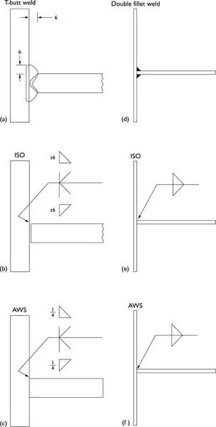
2.5 (a–f) Location of symbols in a T-butt weld and a double fillet weld. ISO dimensions are in millimetres; AWS dimensions are in inches.
Without using weld symbols, Fig. 2.5(a) shows a drawing of a T- butt weld with 6 mm leg length fillet welds and with the edge preparation shown.
Figure 2.5(b) shows the T-butt weld represented by symbols which convey all the information according to the ISO standard.
Figure 2.5(c) shows the T-butt weld indicated by weld symbols for the AWS standard.
If the section ...
Table of contents
- Cover image
- Title page
- Table of Contents
- Copyright page
- Introduction
- Scope
- Standards referred to in this book
- Terms and definitions
- 1: The need to specify welds
- 2: The advantages of symbols
- 3: Welding symbols 1
- 4: Welding symbols 2
- 5: Welding symbols 3
- 6: Location of symbols 1
- 7: Location of symbols 2
- 8: Supplementary symbols
- 9: Dimensions 1
- 10: Dimensions 2
- 11: Dimensions 3
- 12: Spot and seam welds
- 13: Stud welds
- 14: Surfacing
- 15: Process identification
- 16: Non-destructive testing symbols – AWS
- 17: Exercises
Frequently asked questions
Yes, you can cancel anytime from the Subscription tab in your account settings on the Perlego website. Your subscription will stay active until the end of your current billing period. Learn how to cancel your subscription
No, books cannot be downloaded as external files, such as PDFs, for use outside of Perlego. However, you can download books within the Perlego app for offline reading on mobile or tablet. Learn how to download books offline
Perlego offers two plans: Essential and Complete
- Essential is ideal for learners and professionals who enjoy exploring a wide range of subjects. Access the Essential Library with 800,000+ trusted titles and best-sellers across business, personal growth, and the humanities. Includes unlimited reading time and Standard Read Aloud voice.
- Complete: Perfect for advanced learners and researchers needing full, unrestricted access. Unlock 1.5M+ books across hundreds of subjects, including academic and specialized titles. The Complete Plan also includes advanced features like Premium Read Aloud and Research Assistant.
We are an online textbook subscription service, where you can get access to an entire online library for less than the price of a single book per month. With over 1.5 million books across 990+ topics, we’ve got you covered! Learn about our mission
Look out for the read-aloud symbol on your next book to see if you can listen to it. The read-aloud tool reads text aloud for you, highlighting the text as it is being read. You can pause it, speed it up and slow it down. Learn more about Read Aloud
Yes! You can use the Perlego app on both iOS and Android devices to read anytime, anywhere — even offline. Perfect for commutes or when you’re on the go.
Please note we cannot support devices running on iOS 13 and Android 7 or earlier. Learn more about using the app
Please note we cannot support devices running on iOS 13 and Android 7 or earlier. Learn more about using the app
Yes, you can access Welding Symbols On Drawings by E N Gregory,A A Armstrong in PDF and/or ePUB format, as well as other popular books in Technology & Engineering & Materials Science. We have over 1.5 million books available in our catalogue for you to explore.