eBook - ePub
Ultra-Supercritical Coal Power Plants
Materials, Technologies and Optimisation
- 304 pages
- English
- ePUB (mobile friendly)
- Available on iOS & Android
eBook - ePub
About this book
The continued use of coal as a means of generating electricity and an increasing demand for cleaner, more efficient energy production has led to advances in power plant technology. Ultra-supercritical coal power plants reviews the engineering, operation, materials and performance of ultra-supercritical coal power plants.Following a chapter introducing advanced and ultra-supercritical coal power plants, part one goes on to explore the operating environments, materials and engineering of ultra-supercritical coal power plants. Chapters discuss the impacts of steam conditions on plant materials and operation, fuel considerations and burner design, and materials and design for boilers working under supercritical steam conditions. Chapters in part two focus on improving ultra-supercritical coal power plant performance and operability. Ash fouling, deposition and slagging in ultra-supercritical coal power plants are highlighted along with pollution control measures and the estimation, management and extension of the life of ultra-supercritical power plants. Further chapters provide an economic and engineering analysis of a 700°C advanced ultra-supercritical pulverised coal power plant and discuss CO2 capture-ready ultra-supercritical coal power plants.Ultra-supercritical coal power plants is a comprehensive technical reference for power plant operators and engineers, high-temperature materials scientists, professionals in the power industry who require an understanding of ultra-supercritical coal power plants and researchers and academics interested in the field.
- Provides a comprehensive reference on the developments, materials, design and operation of ultra-supercritical power plant
- Considers the degradation issues affecting this type of plant, as well as emissions control and CO2 capture technology; improved plant controls critical to improved operation and environmental performance
- Contains operational assessments for plant safety, plant life management, and plant economics
Trusted by 375,005 students
Access to over 1.5 million titles for a fair monthly price.
Study more efficiently using our study tools.
Information
1
Introduction to advanced and ultra-supercritical fossil fuel power plants
D. Zhang, University of Science and Technology Liaoning, China and The University of Western Australia, Australia
Abstract:
The functioning of the modern society depends increasingly heavily on large-scale, cheap, reliable and clean electricity. Coal has been the king in global electric power production and will continue to serve in this role in the foreseeable future.
Key words
boiler design
high-strength materials
pulverised coal
Rankine cycle
ultra-supercritical steam
1.1 Introduction
Electric power is the most convenient form of energy and is an integral part of modern life. Large-scale electricity generation is done in power plants where a source of primary energy is converted to electrical energy. Steam power plants use fuels such as coal, natural gas or petroleum, which are burned to heat water to create steam. The pressure of the steam spins a turbine that drives the electric generator. Gas turbine power plants use fuels that are burned to create hot gases to spin the turbine. Nuclear power plants use nuclear fission to turn water into steam to drive the turbine. Hydro power plants use the kinetic energy of flowing water to rotate the turbine blades, hence converting kinetic energy into electrical energy. Wind power plants use the wind to push against the blades of the turbine. Geothermal power plants are steam power plants that tap into steam released from the earth. There is also solar energy: either solar-thermal in which solar irradiation is concentrated to generate steam or photovoltaic that uses photoelectric effect to convert light into electricity, and fuel cells that work on the principle of electrochemistry to convert a suitable fuel, via proton/electron exchange, to electricity. In the context of this book, this chapter is only concerned with thermal power plants.
1.1.1 Types of thermal power plant
The most dominant and widespread method of power generation is the steam power plant, or thermal power plant. As the name suggests, thermal power plants convert heat energy into electrical energy.1 The working fluid is mostly steam and they work on the Rankine cycle.2 A steam power plant consists of a boiler which is used to generate the steam from water, a prime mover like a steam turbine to convert the enthalpy of the steam into rotary motion of the turbine which is linked to the alternator to produce electricity. The steam is then condensed in the condenser and fed to the boiler again.
Thermal power plants may be classified in several ways. Based on the type of fuels burnt, they can be classified as coal-fired, gas-fired, oil-fired, or even biomass-fired thermal power plants. The common feature is that a hydrocarbon fuel is burnt with oxygen (air) to raise steam. This feature is also seen in nuclear power plants, some geothermal power plants and solar thermal power plants. This book deals with coal-fired power plants but the same principles can be applied to biomass-based renewable solid fuels. Currently, about 40% of the world’s electricity is generated in coal-fired power plants.1
Depending on the mode of combustion, coal-fired thermal power plants may also be classified1–5 into pulverised fuel (p.f.) fired plants, fluidised-bed (FB) plants, and stock fired plants with a fixed or moving bed of the fuel. In a p.f. boiler,3 coal or biomass is milled (pulverised) into fine powders, blown into the combustion chamber and burnt with the combustion air to release the chemical energy locked in the fuel. The fine p.f. size ensures rapid and highly efficient combustion of the fuel. In a fluidised-bed boiler,4 the fuel is crushed into small particles, typically less than a few millimetres in size and fed into a column combustion chamber where it is burnt with air in a bed material (usually sand) being vigorously agitated (fluidised) by the flowing air. In stock fired boilers,5 the fuel is burnt in lumps, usually several to tens of centimetres in size, on a still or moving grate within the combustion chamber. This book focuses on the p.f. plants.
The Rankine cycle is a thermodynamic cycle which converts heat into work.1,2 The heat from the combustion of p.f. in a furnace is supplied to a closed loop of water/steam as the working fluid. Other common heat sources for thermal power plants using the Rankine cycle are the combustion of natural gas, biomass and oil, solar thermal and nuclear fission. While many substances such as ammonia, chlorinated and fluorinated low hydrocarbons could be used in the Rankine cycle, water is usually the fluid of choice due to its favourable properties, such as nontoxic and non-reactive nature, abundance, and low cost, as well as its thermodynamic properties.
The Rankine cycle is often regarded as a practical Carnot cycle.2 The difference is that in a Rankine cycle a pump is used to pressurise liquid instead of gas. By condensing the fluid to liquid, the work required by the pump only consumes approximately 1–3% of the turbine power, compared to that for compressing a gas in a gas compressor such as in a Carnot cycle. This gives a much higher efficiency for a real cycle. However, the benefit of this is lost somewhat due to the lower heat addition temperature.
Figure 1.1 illustrates the basic working principles of the Rankine cycle in terms of a temperature–entropy (T–S) diagram for a thermal power plant. The working fluid in a Rankine cycle follows a closed loop and is re-used constantly. There are four process steps in the Rankine cycle, each changing the state of the working fluid, identified by the numbers in Fig. 1.1. In Steps 1–2, liquid water is pumped, from low to high pressure and consuming power (WP), into a furnace. Pumping liquid water consumes very little energy compared to compressing gases. In Steps 2–3, the high pressure liquid water absorbs heat (QH) at a constant pressure in the furnace to generate a dry saturated steam. In practice, this dry saturated steam is further superheated before entering the turbines. In Steps 3–4, the superheated steam is expanded to drive the turbines to produce work (WT). This decreases the temperature and pressure of the steam and some condensation may occur. In practice, some of the partially expanded steam is withdrawn from the intermediate stage of the turbines and reheated in the furnace. In Steps 4–1, the wet steam exhausted from the turbines is condensed to become saturated water at a constant pressure and temperature in a condenser to rejected heat (QL) into the environment. The pressure and temperature of the condenser is thermodynamically fixed by the temperature of the cooling reservoir as the fluid is undergoing a phase-change. In an ideal Rankine cycle the pump and turbines would be isentropic, that is, the pump and turbines would generate no entropy and hence maximise the net work output. Process steps 1–2 and 3–4 would be represented by vertical lines on the T–S diagram and more closely resemble that of the Carnot cycle. The Rankine cycle shown here prevents the vapour ending up in the superheated state after the expansion in the turbines, which reduces the energy removed by the condensers.
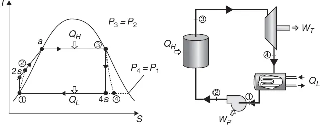
1.1 Thermodynamic principles of Rankine cycle where QH is the heat energy input from the boiler at temperature TH, QL is the heat discharged in the condenser at temperature TL, WP is the pump work input to the recycled water and WT is the net work output.
The Rankine cycle efficiency, defined as the per cent of heat energy input being converted into net work output is
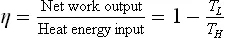
The efficiency of a Rankine cycle is usually limited by the working fluid, the turbine entry temperature and the condenser temperature. The turbine entry temperatures are typically 835 K, being determined by the creep limit of stainless steel,6 and the condenser temperatures are usually around 300 K. This gives a theoretical Carnot efficiency of about 63% compared with an actual efficiency of about 40% for a modern coal-fired power station. This low turbine entry temperature (compared with a gas turbine, which often has an entry temperature of 1773 K) is why the Rankine cycle is often used as a bottoming cycle in combined cycle gas turbine power stations.
In order to increase the Rankine cycle efficiency, one can either increase temperature TH and pressure P3 of steam output from the boiler, or decrease the condenser temperature TL. An increase in boiler pressure results in a higher TH for the same TL, therefore η will increase. TL is often limited by the cooling water reservoir or ambient air temperature. Depending on the temperature and pressure of the steam output from the boiler, thermal power plants can be further classified into7
• conventional subcritical power plant with steam temperature in the vicinity of 820 K and pressure around 16–17 MPa with a plant fuel to electricity conversion efficiency of ca. 38%;
• s...
Table of contents
- Cover image
- Title page
- Table of Contents
- Copyright
- Contributor contact details
- Woodhead Publishing Series in Energy
- Preface
- Acknowledgements
- Chapter 1: Introduction to advanced and ultra-supercritical fossil fuel power plants
- Part I: Operating environments, materials and engineering of ultra-supercritical coal power plants
- Part II: Improving ultra-supercritical coal power plant performance
- Index
Frequently asked questions
Yes, you can cancel anytime from the Subscription tab in your account settings on the Perlego website. Your subscription will stay active until the end of your current billing period. Learn how to cancel your subscription
No, books cannot be downloaded as external files, such as PDFs, for use outside of Perlego. However, you can download books within the Perlego app for offline reading on mobile or tablet. Learn how to download books offline
Perlego offers two plans: Essential and Complete
- Essential is ideal for learners and professionals who enjoy exploring a wide range of subjects. Access the Essential Library with 800,000+ trusted titles and best-sellers across business, personal growth, and the humanities. Includes unlimited reading time and Standard Read Aloud voice.
- Complete: Perfect for advanced learners and researchers needing full, unrestricted access. Unlock 1.5M+ books across hundreds of subjects, including academic and specialized titles. The Complete Plan also includes advanced features like Premium Read Aloud and Research Assistant.
We are an online textbook subscription service, where you can get access to an entire online library for less than the price of a single book per month. With over 1.5 million books across 990+ topics, we’ve got you covered! Learn about our mission
Look out for the read-aloud symbol on your next book to see if you can listen to it. The read-aloud tool reads text aloud for you, highlighting the text as it is being read. You can pause it, speed it up and slow it down. Learn more about Read Aloud
Yes! You can use the Perlego app on both iOS and Android devices to read anytime, anywhere — even offline. Perfect for commutes or when you’re on the go.
Please note we cannot support devices running on iOS 13 and Android 7 or earlier. Learn more about using the app
Please note we cannot support devices running on iOS 13 and Android 7 or earlier. Learn more about using the app
Yes, you can access Ultra-Supercritical Coal Power Plants by Dongke Zhang FTSE in PDF and/or ePUB format, as well as other popular books in Technology & Engineering & Fossil Fuels. We have over 1.5 million books available in our catalogue for you to explore.