- 425 pages
- English
- ePUB (mobile friendly)
- Available on iOS & Android
eBook - ePub
Natural Gas Measurement Handbook
About this book
This information-packed volume covers all aspects of natural gas measurement.
Trusted by 375,005 students
Access to over 1.5 million titles for a fair monthly price.
Study more efficiently using our study tools.
Information
CHAPTER ONE
Introduction
Measurement is the basis of commerce among producers, royalty owners, transporters, process plants, marketers, state and federal government authorities, and the general public.
In fact, measurement of hydrocarbons has a significant impact on the Gross National Product of exporting and importing countries, the financial performance and asset base of global companies, and the perceived efficiency of operating facilities. Given the present or future levels of the cost of these critical resource materials, one can quickly quantify the material and economic value unaccounted for that is associated with each ±0.01% of systematic uncertainty that might unknowingly exist in the measurement systems. The need for accurate fiscal measurement is obvious.
Measurement errors can have both immediate and long-term effects on profits. Inaccurate measurement may result in loss of customers, adverse publicity, potential penalties, and legal liabilities. In short, equitable and accurate measurement is essential to business. It affects the validity of financial and operating reports as well as the corporate reputation.
For these reasons, it is essential that material quantity measurements are precise with minimal bias errors. Furthermore, it is incumbent on those involved in custody transfer to establish and maintain the traceability chains that link their measurements to appropriate domestic and international standards. In this manner, fiscal transfer of materials can be done equitably with the confidence of all parties.
The capital and operating resources (CAPEX and OPEX) applied for fiscal transfers must be commensurate with the total cost of measurement: the capital cost of technology, the operating cost of technology, industry practice or standards, regulatory compliance, and the total fiscal exposure or financial risk (commodity value times throughput).
1.1 Transportation System
The natural gas transportation system (shown in Figure 1-1) covers the gas gathering systems, the gas processing plants, the gas transmission systems, the gas distribution systems, and the various end users.
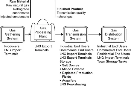
Figure 1-1 Transportation system.
Gas Gathering Systems
The natural gas transportation system begins at the natural gas producing properties. A grid of pipelines throughout the gas producing field gathers the raw material from producing properties or at connecting points of other gathering systems. Compressor stations are located where needed throughout the gird to move the raw material to the gas processing plants. The gas gathering system terminates at the inlet of the gas processing plants. A simplified gas gathering system is shown in Figure 1-2.
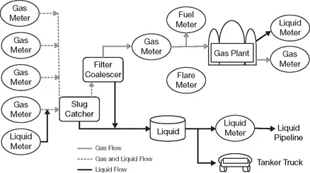
Figure 1-2 Simple gas gathering system.
At the production measurement facility, the fluid is a singlephase gas. A gas gathering system contains liquid pipeline condensate (retrograde and injected condensate). As the gas is transported through the first 5 miles of the system, the system equilibrates to the seabed (or ground) temperature. When the pressure and temperature of the gathering system falls to below the hydrocarbon dew point curve, retrograde condensate is created, forming a two-phase fluid.
Retrograde condensate originates from the drop in gas temperature and pressure due to seabed (or ground) temperatures and pipeline hydraulics. The fluid cannot suspend the same amount of hydrocarbons in the gas phase, resulting in retrograde condensation of liquid hydrocarbons.
One source of injected condensate originates from the processing of the crude oil by the producer to conform to the true vapor limitations contained in the federal environmental regulations. A second source of injected condensate originates from the gas producing properties, which have certain amounts of field condensate.
The measurement of injected condensate into of the gas gathering system uses liquid measurement technology (static or dynamic) in accordance with appropriate industry standards.
Gas gathering systems, by their physics, exhibit multiphase flow due to the presence of liquid pipeline condensate, free water, and liquid methanol (hydrate prevention).
For gas gathering systems, the frequency of pigging dictates the amount of pipeline condensate received into the slug catcher and coalescer separator. A rigorous pigging program is required to ensure the liquid quantities do not exceed the design capacity of the system.
The pipeline condensate may be processed by the gas plant or transported to other industrial customers (refineries and chemical plants) as an intermediate product (field condensate).
At the inlet to the gas processing plant, the best practice is to install slug catchers in combination with coalescer separators immediately followed by a single-phase gas measurement facility. This capital-intensive equipment ensures the presence of singlephase gas for the custody transfer.
At the end of the gas gathering system, the pipeline condensate (retrograde and injected condensate) employs liquid measurement technology (static or dynamic) in accordance with the appropriate industry standards. For small pipeline condensate throughputs, tank trucks are employed to transport the raw material to other consuming and processing plants. For large pipeline condensate throughputs, liquid pipelines transport the raw material to other consuming and processing plants.
Complex gas gathering systems (see Figure 1-3) involve gathering pipeline interconnections upstream of the gas processing plant.
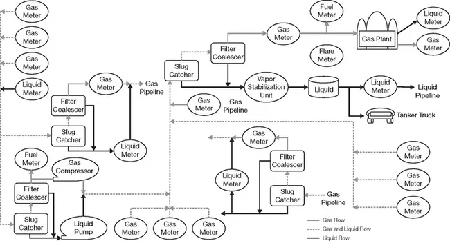
Figure 1-3 Complex gas gathering system.
Interconnections without Pipeline Condensate Injection
For complex systems involving pipeline interconnections that do not allow the injection of pipeline condensate, the best practice is to install a slug catcher followed by a liquid-gas separator immediately followed by a single-phase gas measurement facility. This ensures the presence of single-phase gas for the custody transfer.
The pipeline condensate (liquids from the slug catcher and liquid-gas separator) is returned to the originating gas gathering system.
Interconnections with Pipeline Condensate Injection
For complex systems involving pipeline interconnections that allow the injection of pipeline condensate, the best practice is to install a slug catcher followed by a liquid-gas separator immediately followed by a single-phase gas measurement facility. This ensures the presence of single-phase gas for the custody transfer.
The pipeline condensate (liquids from the slug catcher and liquid-gas separator) is measured using liquid dynamic technologies and practices.
Gas Processing Plants
Gas processing plants (see Figure 1-4) take the raw material (natural gas, pipeline condensate, water, hydrogen sulfide, and sulfur) and generate intermediate products (raw make, plant condensate, natural gasoline, and ethane-propane streams) and finished products (transmission quality natural gas, butane, and propane).
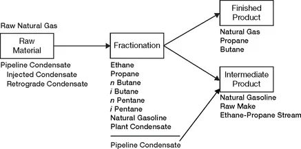
Figure 1-4 Gas processing plant.
Gas processing plants employ fractionation processes to convert the raw material (gas gathering system) to intermediate and finished products.
The intermediate products are transported to other processing plants (refineries and chemical plants) through dedicated p...
Table of contents
- Cover image
- Title page
- Table of Contents
- Copyright
- Dedication
- List of Tables
- List of Figures
- Preface
- Symbols
- Unit Conversions
- CHAPTER ONE: Introduction
- CHAPTER TWO: Composition and Quality
- CHAPTER THREE: Physical Properties and Process Conditions
- CHAPTER FOUR: Measurement Concepts
- CHAPTER FIVE: Orifice Flowmeter
- CHAPTER SIX: Ultrasonic Flowmeter
- CHAPTER SEVEN: Turbine Flowmeter
- CHAPTER EIGHT: Rotary Displacement Flowmeter
- CHAPTER NINE: Calculations
- CHAPTER TEN: Secondary and Tertiary Devices
- CHAPTER ELEVEN: Electronic Gas Measurement
- CHAPTER TWELVE: Uncertainty
- CHAPTER THIRTEEN: Measurement System Design
- CHAPTER FOURTEEN: Orifice Flowmeter Design
- CHAPTER FIFTEEN: Ultrasonic Flowmeter Design
- CHAPTER SIXTEEN: Turbine Flowmeter Design
- CHAPTER SEVENTEEN: Rotary Displacement Flowmeter Design
- CHAPTER EIGHTEEN: Inspection, Testing, Verification, Calibration, and Certification
- APPENDIX: Standards, Publications, and Regulations
- Glossary
- Index
Frequently asked questions
Yes, you can cancel anytime from the Subscription tab in your account settings on the Perlego website. Your subscription will stay active until the end of your current billing period. Learn how to cancel your subscription
No, books cannot be downloaded as external files, such as PDFs, for use outside of Perlego. However, you can download books within the Perlego app for offline reading on mobile or tablet. Learn how to download books offline
Perlego offers two plans: Essential and Complete
- Essential is ideal for learners and professionals who enjoy exploring a wide range of subjects. Access the Essential Library with 800,000+ trusted titles and best-sellers across business, personal growth, and the humanities. Includes unlimited reading time and Standard Read Aloud voice.
- Complete: Perfect for advanced learners and researchers needing full, unrestricted access. Unlock 1.5M+ books across hundreds of subjects, including academic and specialized titles. The Complete Plan also includes advanced features like Premium Read Aloud and Research Assistant.
We are an online textbook subscription service, where you can get access to an entire online library for less than the price of a single book per month. With over 1.5 million books across 990+ topics, we’ve got you covered! Learn about our mission
Look out for the read-aloud symbol on your next book to see if you can listen to it. The read-aloud tool reads text aloud for you, highlighting the text as it is being read. You can pause it, speed it up and slow it down. Learn more about Read Aloud
Yes! You can use the Perlego app on both iOS and Android devices to read anytime, anywhere — even offline. Perfect for commutes or when you’re on the go.
Please note we cannot support devices running on iOS 13 and Android 7 or earlier. Learn more about using the app
Please note we cannot support devices running on iOS 13 and Android 7 or earlier. Learn more about using the app
Yes, you can access Natural Gas Measurement Handbook by James E. Gallagher in PDF and/or ePUB format, as well as other popular books in Technology & Engineering & Fossil Fuels. We have over 1.5 million books available in our catalogue for you to explore.