eBook - ePub
Fatigue Analysis of Welded Components
Designer's Guide to the Structural Hot-Spot Stress Approach
- 56 pages
- English
- ePUB (mobile friendly)
- Available on iOS & Android
eBook - ePub
Fatigue Analysis of Welded Components
Designer's Guide to the Structural Hot-Spot Stress Approach
About this book
This report provides background and guidance on the use of the structural hot spot stress approach to the fatigue design of welded components and structures. It complements the IIW recommendations for 'Fatigue Design of Welded Joints and Components' and extends the information provided in the IIW recommendations on 'Stress Determination for Fatigue Analysis of Welded Components'. This approach is applicable to cases of potential fatigue cracking from the weld toe. It has been in use for many years in the context of tubular joints. The present report concentrates on its extension to structures fabricated from plates and non-tubular sections.Following an explanation of the structural hot spot stress, its definition and its relevance to fatigue, the authors describe methods for its determination. Stress determination from both finite element analysis and strain gauge measurements is considered. Parametric formulae for calculating stress increases due to misalignment and structural discontinuities are also presented. Special attention is paid to the use of finite element stress analysis and guidance is given on the choice of element type and size for use with either solid or shell elements. Design S-N curves for use with the structural hot spot stress are presented for a range of weld details. Finally, practical application of the recommendations is illustrated in two case studies involving the fatigue assessment of welded structures using the structural hot spot stress approach.
- Provides practical guidance on the application of the structural hot-spot stress approach
- Discusses stress determination from both finite element analysis and strain gauge measurements
- Practical application of the recommendations is illustrated in two case studies
Trusted by 375,005 students
Access to over 1.5 million titles for a fair monthly price.
Study more efficiently using our study tools.
Information
1
Introduction
1.1 General
Traditional fatigue analysis of welded components is based on the use of nominal stresses and catalogues of classified details. A particular type of detail is assigned to a particular fatigue class with a given S-N curve. Such a method is used in the IIW fatigue design recommendations (1). This nominal stress approach ignores the actual dimensional variations of a particular structural detail, which is an obvious drawback. Moreover, the form of a welded component is often so complex that the determination of the nominal stress is difficult or impossible. This is true even if the finite element analysis (FEA) method is used for the stress analysis.
In the context of potential fatigue failure by crack growth from the weld toe or end, the structural hot spot stress approach goes one step forward. Here the calculated stress does take into consideration the dimensions of the detail. The resulting structural stress at the anticipated crack initiation site (‘hot spot’) is called the structural hot spot stress. Structural stress includes the stress concentrating effects of the detail itself but not the local non-linear stress peak caused by the notch at the weld toe. This notch effect is included in the hot spot S-N curve determined experimentally. This is reasonable because the exact geometry of the weld will not be known at the design stage. The variation in the local geometry of the weld toe is one of the main reasons for scatter in fatigue test results. By using the lower-bound characteristic S-N curve, lower bound quality of the weld toe is incorporated into the analysis. A single S-N curve should suffice for most forms of structural discontinuity, providing the weld toe geometry is always the same.
An obvious reason for introducing the structural hot spot approach is the availability of powerful computers and software, which make detailed FEA possible for most design offices. However, the approach is also a valuable tool for choosing the locations of strain gauges when validating design by field-testing prototype structures. Moreover, finite element analyses make it possible to produce parametric formulae in advance for easy estimation of structural stresses at various hot spots.
The hot spot approach was first developed for fatigue analysis of welded tubular joints in offshore structures. Corresponding fatigue design rules were published by the American Petroleum Institute, the American Welding Society, Bureau Veritas, UK Department of Energy, etc. A review of this topic can be found in Ref. (2). There is now an increasing demand for application of the approach to be extended to all kinds of plated structures. Some progress has been made in doing this, but at present there are differences in the methods recommended for estimating the structural hot spot stress.
The first general design rule to include the structural stress (referred to at the time as the geometric stress) approach was the European pre-standard ENV 1993-1-1 (3) (Eurocode 3) but only limited guidance was given. Later, the International Institute of Welding (IIW) published new recommendations containing four fatigue design approaches, including the hot spot approach (1). A background document was also published focusing on definitions and the determination of stresses used in the fatigue analysis of welded components (4).
Subsequently, further research has led to improved procedures for determining the structural hot spot stress, particularly using FEA (5,6), and the provision of background fatigue test data from which to derive suitable design S-N curves (7-10). Furthermore, the ability to establish through-thickness stress distributions using FEA has enabled a method to be developed that uses this information to calculate the structural hot spot stress. Previously attention has focussed on use of the surface stress distribution, approaching the weld in question, and determination of the structural hot spot stress using an extrapolation procedure. Use of the through-thickness stress distribution instead should avoid the need for extrapolation.
The goal of the present document is to help design engineers and stress analysts to implement the structural hot spot stress approach in practice. Symbols and terms are defined as they are used but symbols are also defined in Appendix 1. Practical examples of the application of the methods described are given in the form of Case Studies in Sections 6 and 7. Moreover, the document should serve as a reference when detailed guidelines for design are developed for particular welded products. The recommendations given here are intended for design of general welded structures subjected to fatigue loading. The document is mainly focused on plated structures, such as bridges, cranes, earth moving machinery, ship hulls, etc. Specific rules are already available for certain fields of application, including tubular structures (11), ship hulls (12,13) and pressure vessels (14).
In view of the scope of current experience and the availability of relevant fatigue test data, the recommendations presented in this document are only intended for plate thicknesses above 4 mm.
1.2 Safety aspects
When using this document the general guidelines on fatigue analysis and safety aspects given in the latest version of the IIW Recommendations (1) should be taken into consideration. For example, it may be appropriate to multiply the fatigue loads by a partial safety factor, γF, which will normally be specified in the appropriate design code for a particular structure. Similarly, the fatigue strength may need to be divided by γM, as required.
It should be noted that the S-N curves presented in this document do not include any allowance for inaccuracies in stress determination. Furthermore, the stress raising effect of misalignment in welded joints and other such imperfections may not have been taken into account. If the stress analyst chooses to simplify the stress determination, for example by omitting the extrapolation of the structural stress to the weld toe or by totally neglecting misalignment, the load factor, γF, should be increased accordingly.
The linear extrapolation technique for approximation of the structural stress at the hot spot (to be described later) may sometimes under-estimate the structural hot spot stress. Therefore, more accurate techniques for stress determination are recommendable for critical components that require a high safety margin, see Appendix 2.
2
The Structural Hot Spot Stress Approach to Fatigue Analysis
2.1 Field of application
The structural hot spot stress approach applies to welded joints for which:
• The fluctuating principal stress acts predominantly transverse to the weld toe (or the ends of a discontinuous longitudinal weld);
• the potential fatigue crack will initiate at the weld toe or end.
Referring to Fig.2.1, the hot spot approach applies to cases a to e. For reasons that will be discussed later, it is also necessary to distinguish between joints that are fully load-carrying and non-load-carrying. Cases c) and h) represent load-carrying fillet welds, whereas case b) represents non-load carrying fillet welds. Fillet welds at cover and collar plates (lugs), case d), are also treated as non-load carrying welds. End welds in cases e) and j), representing gussets or brackets welded on plates, are considered as non-load-carrying. If there is any doubt about the choice of category, the joint should be assumed to be load-carrying. The approach is not applicable to cases where the crack will grow from the weld root and propagate through the weld throat, cases f) to i) in Fig.2.1. Good design practice aims to avoid this kind of behaviour because the crack is not visible before it has propagated through the weld. Moreover, the structural hot spot approach does not apply to continuous welds subject to longitudinal loading. The nominal stress approach (1) is sufficient for such cases.
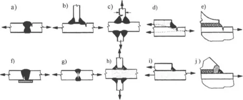
2.1 Examples of fatigue crack initiation sites in welded joints
The weld detail being assessed will often be situated in a bi-axial stress field. Then it is usually sufficient to apply the structural stress approach to that principal stress which is acts approximately perpendicular (between 30° and 90°) to the weld toe, see Section 2.3. If necessary, the other principal stress can be considered using the fatigue class for longitudinally loaded welds in the nominal stress approach according to Ref. (1).
2.2 Types of hot spot
Hot spots can be classified as two types, as shown in Fig.2.2:
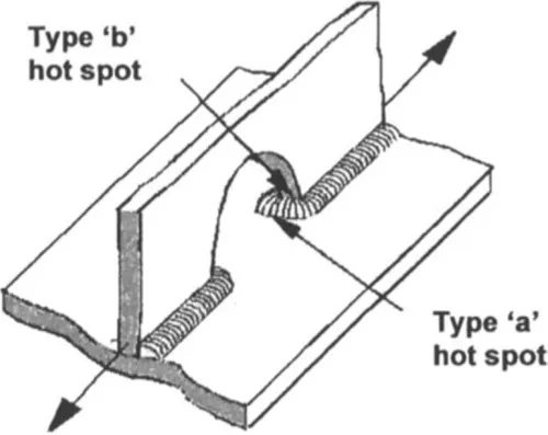
2.2 Examples of the two hot spot types, in a welded girder:
Type ‘a’ is located on the surface of the lower flange.
Type ‘b’ is located on the edge of the web plate in the scallop
| Type ‘a’ | The weld is located on a plate surface, see also Fig.2.1 a) – d). |
| Type ‘b’ | The weld is located on a plate edge, see also Fig.2.3. |
Diffe...
Table of contents
- Cover image
- Title page
- Table of Contents
- Copyright page
- Preface
- Abstract
- 1: Introduction
- 2: The Structural Hot Spot Stress Approach to Fatigue Analysis
- 3: Experimental Determination of the Structural Hot Spot Stress
- 4: Structural Hot Spot Stress Determination Using Finite Element Analysis
- 5: Parametric Formulae
- 6: Structural Hot Spot S-N Curves
- 7: Case Study 1: Box Beam of a Railway Wagon
- 8: Case Study 2: Hatch Corner Design for Container Ships
- 9: References
- Appendix 1: Symbols
- Appendix 2: A2.4 References
- Appendix 3: References
- Appendix 4: Hot Spot S-N Curves for Welded Aluminium Components
Frequently asked questions
Yes, you can cancel anytime from the Subscription tab in your account settings on the Perlego website. Your subscription will stay active until the end of your current billing period. Learn how to cancel your subscription
No, books cannot be downloaded as external files, such as PDFs, for use outside of Perlego. However, you can download books within the Perlego app for offline reading on mobile or tablet. Learn how to download books offline
Perlego offers two plans: Essential and Complete
- Essential is ideal for learners and professionals who enjoy exploring a wide range of subjects. Access the Essential Library with 800,000+ trusted titles and best-sellers across business, personal growth, and the humanities. Includes unlimited reading time and Standard Read Aloud voice.
- Complete: Perfect for advanced learners and researchers needing full, unrestricted access. Unlock 1.5M+ books across hundreds of subjects, including academic and specialized titles. The Complete Plan also includes advanced features like Premium Read Aloud and Research Assistant.
We are an online textbook subscription service, where you can get access to an entire online library for less than the price of a single book per month. With over 1.5 million books across 990+ topics, we’ve got you covered! Learn about our mission
Look out for the read-aloud symbol on your next book to see if you can listen to it. The read-aloud tool reads text aloud for you, highlighting the text as it is being read. You can pause it, speed it up and slow it down. Learn more about Read Aloud
Yes! You can use the Perlego app on both iOS and Android devices to read anytime, anywhere — even offline. Perfect for commutes or when you’re on the go.
Please note we cannot support devices running on iOS 13 and Android 7 or earlier. Learn more about using the app
Please note we cannot support devices running on iOS 13 and Android 7 or earlier. Learn more about using the app
Yes, you can access Fatigue Analysis of Welded Components by E. Niemi,W Fricke,S J Maddox in PDF and/or ePUB format, as well as other popular books in Technology & Engineering & Mechanical Engineering. We have over 1.5 million books available in our catalogue for you to explore.