- 834 pages
- English
- ePUB (mobile friendly)
- Available on iOS & Android
eBook - ePub
System Requirements Analysis
About this book
System Requirements Analysis gives the professional systems engineer the tools to set up a proper and effective analysis of the resources, schedules and parts needed to successfully undertake and complete any large, complex project. This fully revised text offers readers the methods for rationally breaking down a large project into a series of stepwise questions, enabling you to determine a schedule, establish what needs to be procured, how it should be obtained, and what the likely costs in dollars, manpower, and equipment will be to complete the project at hand.
System Requirements Analysis is compatible with the full range of popular engineering management tools, from project management to competitive engineering to Six Sigma, and will ensure that a project gets off to a good start before it's too late to make critical planning changes. The book can be used for either self-instruction or in the classroom, offering a wealth of detail about the advantages of requirements analysis to the individual reader or the student group.
- Written by the authority on systems engineering, a founding member of the International Council on Systems Engineering (INCOSE)
- Complete overview of the basic principles of starting a system requirements analysis program, including initial specifications to define problems, and parameters of an engineering program
- Covers various analytical approaches to system requirements, including structural and functional analysis, budget calculations, and risk analysis
Trusted by 375,005 students
Access to over 1.5 million titles for a fair monthly price.
Study more efficiently using our study tools.
Information
1
Introduction
The first chapter begins with an introduction to the work this volume focuses on. Many of the subject-matter words the reader will find throughout the book are defined and explained. One of the key ideas that supports the use of the word “affordability” is that the book encourages the use of models and shows ways that all requirements appearing in all specifications can be derived from models and in the second section we will introduce the idea of modeling. Requirements work is what a program begins with, so it is appropriate to discuss the management infrastructure within which it and later program phases will occur. Some variations on a central theme are also discussed. Closing out this chapter will be an insight into a proposed prescription for achieving an effective system development process that is affordable to apply while producing good program results.
The overall objective of the book is to show system engineers how to accomplish the early program work related to developing the program peculiar specifications needed to define the problem that must be solved through design, procurement, and manufacture. A companion volume titled “System Verification” completes the story by covering how a program may determine and to what extent the manufactured product complies with the content of the specifications.
The book and its first chapter begin with an introduction to the work this volume focuses on. Many of the subject matter words the reader will find throughout the book are defined and explained. One of the key ideas that support the use of the word “affordability” is that the book encourages the use of models and shows ways that all requirements appearing in all specifications can be derived from models and in the second chapter we will introduce the idea of modeling. Requirements work is what a program begins with so it is appropriate to discuss the management infrastructure within which it and later program phases will occur. Some variations on a central theme are also discussed. Closing out this chapter will be an insight into a proposed prescription for achieving an effective system development process that is affordable to apply while producing good program results.
The overall objective of the book is to show system engineers how to accomplish the early program work related to developing the program-peculiar specifications needed to define the problem that must be solved through design, procurement, and manufacture. A companion volume titled “System Verification” completes the story by covering how a program may determine to what extent the manufactured product complies with the content of the specifications.
1.1 Introduction to Systems Requirements
1.1.1 What Is a System?
This book deals with man’s efforts to develop systems. Many definitions of the word system have been offered, but in the broadest and most simple sense, any two or more entities interacting cooperatively to achieve some common goal, function, or purpose constitutes a system. Thus systems are composed of entities that interact together through relationships and with their environment. The content of this book applies most appropriately to man-made systems that are organized collections of entities that interact synergistically via the interfaces connecting them to achieve preplanned goals in accordance with a predetermined plan or process. Generally, in these kinds of systems, no subset of the system resources operating independently can totally achieve the same system goal or purpose, because we tend to create them in a least-cost configuration. The key to system existence, and the superior performance of a system over an unorganized collection of independent objects, is the purposeful cooperative interaction that occurs among the multiple system resources via the interfaces that connect them. So any one system must consist of entities interconnected by relationships, most often referred to as interfaces. A system also interacts with its environment through interfaces.
There exist natural systems in our universe, such as the ultimate system, the universe itself, the climatic system on Earth, and the human circulatory system. These systems evolved through natural processes not requiring any human engineering activity, and a good thing because there were no humans when many of these systems evolved. Some readers may prefer to recognize that natural systems were actually put in place by God. The author neither poses a counterargument to that premise nor recognizes that there would be any significant difference in the content of this book if that were the case. Natural systems can be characterized using techniques described in this book, but we must recognize one fundamental difference between natural and man-made systems. Natural systems are not designed by people, they simply must be understood and described by people and this is perhaps more of a job for scientists than engineers.
This situation is changing, however. We are manipulating natural systems to an increasingly powerful extent, bordering on redesign on a small scale. As a result, there will likely be an increasing application in the future for organized system engineering methods in natural system fields like biotechnology, agronomy, weather, and aquifers. The requirements impact analysis approach discussed in this book in association with engineering change proposals and environmental requirements analysis may apply to these situations more than we would care to think about. A TRW (Thompson, Ramo, Woolridge who were the three gentlemen forming this company) systems engineer working on the Yucca Mountain nuclear waste storage site once told the author that the developer first had to identify the degree of isolation provided between the stored material and the local aquifer offered by government furnished property (GFP) before determining what man-made features were required. The author asked how GFP was involved and the engineer replied—“No, God-furnished property.”
A man-made system is developed to achieve a preplanned function, goal, or purpose. These systems require engineering development work to convert the preplanned function, goal, or purpose into a practical solution composed of physical hardware elements that can be manufactured and assembled from available materials. Most often, these systems will also include computer software and, commonly, human operators who interact with the hardware and software to guide the system toward its function, goal, or purpose. Finally, these systems will include relationships implemented through interfaces between the product entities composing the system. Figure 1.1 shows three ways systems are illustrated at the very top level and related to their environment using models that we will discuss in this book.
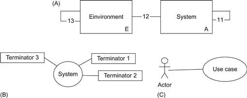
Figure 1.1 The ultimate system abstraction. (A) traditional, (B) modern structured analysis, and (C) unified modeling language.
Figure 1.1A illustrates the ultimate abstraction for a system in the form of a single block that represents the complete system. It interacts with a system environment and internally within itself to achieve the system function, goal, or purpose. To simplify this phrase let us agree to simply refer to the function of a system being its goal or purpose. The system environment consists of everything that influences the system that exists in the Universe, less the system itself. The system function, stated in a customer need statement, is the requirement that is assigned to the system block in this diagram. It is the ultimate requirement for the system that can be mindlessly brought into imaginary existence by the allocation of the customer need to an entity called the system. We often speak of decomposition of the system need, and this is where the decomposition process starts, with the ultimate requirement. The two fundamental blocks shown in Figure 1.1 are interrelated by three different kinds of interfaces identified as I1, I2, and I3 that will be explained in a later section.
Using a functional modeling process we can progressively decompose or partition the functionality represented by the need into lower-tier functionality as a means of gaining insight into what the system and its parts must accomplish and how well it and its many elements must perform. The decomposition process stops when we have identified all of the system resources that will yield to detailed design by a single design agent or team in the producing enterprise or can be procured from a single supplier. In the late 1990s, the author, trying to impress a manager on the International Thermonuclear Experimental Reactor (ITER) program, then based in La Jolla, California, and thus encourage him to purchase a system engineering training program, showed the manager his schematic block diagram (SBD) of the universe. The author, thinking that the universe included everything there was, illustrated only one block on the diagram containing everything rather than the two-block arrangement shown in Figure 1.1A. The diagram in question will appear in the section dealing with environmental requirements analysis. The manager looked at the diagram briefly and said, “You may have forgotten a few wormholes.” A contract was not forthcoming so that may not have been a good marketing technique. Chapter 3 of this book covers the functional analysis (FA) approach depicted in Figure 1.1A in considerable detail. Performance requirements are derived from functions and allocated to product entities thereby identifying lower-tier system entities.
Figure 1.1B offers the ultimate system view from the perspective of an adherent of modern structured analysis (MSA) used for many years, and to this day, by some to develop computer software. The system, whatever it may become during the development process, is shown interacting with several (three in this case) external entities called terminators. This is a very useful diagram no matter what modeling approach one might employ. A context diagram can also be used to identify all of the parties interested in the development effort, often called stakeholders. In the case of MSA these terminators relate to sources and destinations of information. When we extend MSA to the process for system architecture and requirements engineering (PSARE), initially called Hatley–Pirbhai modeling, in Chapter 4 we will find that the terminators can be information, energy, or material because PSARE was developed so as not be limited to software development as MSA was intended.
Figure 1.1C illustrates a system from the perspective of an adherent of system modeling language (SysML) or unified modeling language (UML). Actors interact with the system through what are called use cases achieving specific benefits in so doing. Modeling artifacts are then employed to describe these benefits from which requirements are derived. Chapter 4 also covers the model depicted in Figure 1.1C.
This book covers three comprehensive modeling approaches coordinated with the three top-end views in Figure 1.1. A forth modeling approach, also addressed in the book involves over 50 modeling artifacts and the author cannot think of a simple view of the overall process that could be included in Figure 1.1. The U.S. Department of Defense (DoD) has shown great interest in a development model named DoDAF for DoD Architecture Framework. This interest has been extended through cooperation with the UK Ministry of Defence (MOD) under the acronym MODAF. It was initially developed to model large-scale information systems but was initially not appropriate as a comprehensive general system modeling approach like the other three brought together in Chapter 6. Chapter 4 provides an overview of this process in the interest of completeness and recognizes the continuing work being done since 2004 by the Unified Process for DoDAF MoDAF (UPDM) RFC Group composed of several companies in cooperation with the U.S. DoD and UK MOD to advance the use of the modeling artifacts of UML-SysML rather than whatever modeling artifacts the customer, team, or program prefers. In Section 6.5, we also extend the model so that it may be used as a single model that can be used to define the system architecture and support derivation of all requirements that will populate specifications no matter how the system is to be implemented in terms of hardware, software, and people doing things.
The author maintains that all requirements appearing in specifications should be derived through modeling. The author’s set of comprehensive modeling approaches started with three useful models for doing this work covered in Chapters 3 through 5 with the beginnings for them noted in Figure 1.1. With the emergence of UPDM the author has grudgingly added it to form a forth comprehensive modeling approach from which an enterprise may select a single model and encourage its employees to become proficient in using that one model on all programs.
The book focuses the modeling artifacts thus described on four specific universal architecture description frameworks (UADFs) in Chapter 6 and offers encouragement that a systems development enterprise select one, coordinate it with an effective tool set, qualify its employees to effectively use the selected modeling methods and selected tools, and manage the whole well. In a nutshell, this is the beginning of the prescription for achieving affordability and success in requirements and verification. Chapter 6 offers an extended version of UPDM as a forth UADF such that an enterprise required by contract to employ DoDAF may use the UPDM version extended to include modeling elements that support environmental and specialty engineering modeling to also support specification content development in a single modeling approach.
The modeling capability of the problem space components of these four UADF are effective in: (1) identifying needed functionality or behavior, (2) deriving appropriate performance requirements from that functionality, (3) identifying the product entities that the system should consist of, and (4) identifying the interface relationships that will have to exist between the product entities and between the system and its environment. We will have to add to each of the first three UADF an additional trio of solution space models to complete the work begun under the problem space components of these three UADF. The three problem space models are covered in Chapters 3 and 4. In addition to these modeling capabilities they must be combined with the solution space models covered in Chapter 5 for interface, specialty engineering, and environmental requirements though MSA-PSARE, UML-SysML (and therefore UPDM) do include adequate interface modeling capability. All or parts of these three models can be coordinated with any of the three UADF to form four complete models each one of which is comprehensive meaning that it may be used to derive all requirements for all entities in a system no matter how we decide to implement the system in terms of hardware, software, and people doing things. These four UADF are then brought together in Chapter 6.
1.1.2 Types of Systems
The central premi...
Table of contents
- Cover image
- Title page
- Table of Contents
- Copyright
- List of Illustrations
- List of Tables
- List of Acronyms
- Preface
- 1. Introduction
- 2. Requirements Foundation
- 3. The Functional Problem Space Model
- 4. A Variety of Software Models
- 5. Joint Solution Space Modeling
- 6. Universal Architecture Description Frameworks
- 7. Specification Content Standards
- 8. Requirements Management
- 9. Computer Applications
- 10. Closing
- Bibliography
Frequently asked questions
Yes, you can cancel anytime from the Subscription tab in your account settings on the Perlego website. Your subscription will stay active until the end of your current billing period. Learn how to cancel your subscription
No, books cannot be downloaded as external files, such as PDFs, for use outside of Perlego. However, you can download books within the Perlego app for offline reading on mobile or tablet. Learn how to download books offline
Perlego offers two plans: Essential and Complete
- Essential is ideal for learners and professionals who enjoy exploring a wide range of subjects. Access the Essential Library with 800,000+ trusted titles and best-sellers across business, personal growth, and the humanities. Includes unlimited reading time and Standard Read Aloud voice.
- Complete: Perfect for advanced learners and researchers needing full, unrestricted access. Unlock 1.5M+ books across hundreds of subjects, including academic and specialized titles. The Complete Plan also includes advanced features like Premium Read Aloud and Research Assistant.
We are an online textbook subscription service, where you can get access to an entire online library for less than the price of a single book per month. With over 1.5 million books across 990+ topics, we’ve got you covered! Learn about our mission
Look out for the read-aloud symbol on your next book to see if you can listen to it. The read-aloud tool reads text aloud for you, highlighting the text as it is being read. You can pause it, speed it up and slow it down. Learn more about Read Aloud
Yes! You can use the Perlego app on both iOS and Android devices to read anytime, anywhere — even offline. Perfect for commutes or when you’re on the go.
Please note we cannot support devices running on iOS 13 and Android 7 or earlier. Learn more about using the app
Please note we cannot support devices running on iOS 13 and Android 7 or earlier. Learn more about using the app
Yes, you can access System Requirements Analysis by Jeffrey O. Grady in PDF and/or ePUB format, as well as other popular books in Technology & Engineering & Industrial Engineering. We have over 1.5 million books available in our catalogue for you to explore.