eBook - ePub
Radio-Frequency Digital-to-Analog Converters
Implementation in Nanoscale CMOS
- 302 pages
- English
- ePUB (mobile friendly)
- Available on iOS & Android
eBook - ePub
Radio-Frequency Digital-to-Analog Converters
Implementation in Nanoscale CMOS
About this book
With the proliferation of wireless networks, there is a need for more compact, low-cost, power efficient transmitters that are capable of supporting the various communication standards, including Bluetooth, WLAN, GSM/EDGE, WCDMA and 4G of 3GPP cellular. This book describes a novel idea of RF digital-to-analog converters (RFDAC) and demonstrates how they can realize all-digital, fully-integrated RF transmitters that support all the current multi-mode and multi-band communication standards.
With this book the reader will:
- Understand the challenges of realizing a universal CMOS RF transmitter
- Recognize the design issues and the advantages and disadvantages related to analog and digital transmitter architectures
- Master designing an RF transmitter from system level modeling techniques down to circuitdesigns and their related layout know-hows
- Grasp digital polar and I/Q calibration techniques as well as the digital predistortion approaches
- Learn how to generate appropriate digital I/Q baseband signals in order to apply them to the test chip and measure the RF-DAC performance.
- Highlights the benefits and implementation challenges of software-defined transmitters using CMOS technology
- Includes various types of analog and digital RF transmitter architectures for wireless applications
- Presents an all-digital polar RFDAC transmitter architecture and describes in detail its implementation
- Presents a new all-digital I/Q RFDAC transmitter architecture and its implementation
- Provides comprehensive design techniques from system level to circuit level
- Introduces several digital predistortion techniques which can be used in RF transmitters
- Describes the entire flow of system modeling, circuit simulation, layout techniques and the measurement process
Trusted by 375,005 students
Access to over 1.5 million titles for a fair monthly price.
Study more efficiently using our study tools.
Information
Chapter 1
Introduction
Abstract
The reasons for writing this book are outlined in this introductory chapter. The conventional radio has too many components, which are bulky, costly, and consume too much power. Further, the technology used tends not to be aligned with the deep nanoscale CMOS used by digital processors. Hence, a new digitally intensive wideband in-phase/quadrature transmitter architecture is proposed to remove the aforementioned handicaps and to promote further progress. The chapter then gives necessary background to understand the system-level aspects of wireless transmitters and qualitatively compares the new architecture with prior art.
Keywords
Multimode; Multiband; Transmitter architecture; Radio integration; Technology scaling; Analog-intensive transmitter; Digitally intensive transmitter; Polar topology; Cartesian topology; Nanoscale CMOS
Consumer electronic devices such as smartphones, tablets, and laptops are constantly evaluated against three key criteria: low-cost, high-power efficiency, and support of multimode/multiband communication standards such as Wi-Fi or wireless LAN (IEEE 802.11) [1], Bluetooth [2], GNSS,1 second-generation (2G) cellular using GSM, third-generation (3G) cellular using WCDMA [3], and fourth-generation (4G) cellular using either of WiMAX or 3GPP LTE [4, 5]. These gadget devices comprise a myriad of IC chips to perform an extensive number of distinct functions such as multimedia streaming and gaming as well as supporting the aforementioned communication standards. As an example of contemporary gadget devices, Fig. 1.1 illustrates the mainboard of a smartphone, for example, the iPhone 5. It consists of an application processor (AP) unit, subscriber identification module (SIM) card slot, NAND flash memory, power management unit, Class-D audio amplifier, and, most significantly, a number of RF transceiver modules that support today’s universal communication standards such as GSM, CDMA, Wi-Fi/Bluetooth/FM, GPS, and LTE in combination with its power management unit. Over the past two decades, there have been tremendous efforts to design RF radios that will afford an opportunity to address the low-power, low-cost, and extremely power-efficient demands and, yet, they have also employed inventive transceiver architectures.

1.1 The Conventional RF Radio
As depicted in Fig. 1.2A, a conventional RF transceiver consists of a baseband DSP unit, TX, and RX [6, 7]. The transmitter performs in the following manner: The anticipated transmitted information such as voice, video, or digital data like text/images are initially digitally processed, then encoded, and subsequently applied to a DAC in order to convert the digital data to their corresponding analog counterparts. Due to the fact that these analog signals comprise unwelcome noise and spectral replicas, the transmitter utilizes a low-pass filter (LPF) to reduce those undesirable artifacts. The filtered analog signals are subsequently mixed with an RF LO utilizing an upconverting mixer and, consequently, upconverted to their designated RF transmit frequency band. Otherwise stated, as illustrated in Fig. 1.2B, the LO signal translates the low-frequency baseband analog signals with the bandwidth of ωBB into their equivalent high-frequency RF representation. In fact, the LO clock modulates the baseband signal. Thus, the upconverting RF mixer is referred to as an RF modulator. A PA is succeedingly employed to efficiently boost the RF signal. The subsequent RF amplified signal is then applied to either a duplexer or transmit/receive (T/R) switch2 in order to be delivered to the transmitting antenna.
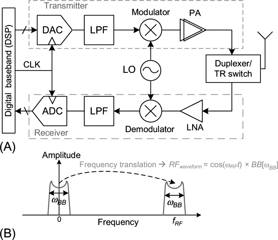
In the receiver, however, its sensitivity is ameliorated utilizing a low-noise amplifier (LNA). The subsequent signal is then down converted to baseband frequency utilizing a down-converter mixer, which is also referred to as a demodulator. By employing a few LPF circuits and then an ADC, the received signal is digitized for further digital baseband-processing operation.
Among transceiver blocks, the RF transmitter is considered to be the most power consuming block of the entire radio, thus being a hindrance for extending the battery lifetime of portable wireless devices. This is due to the fact that it comprises power hungry building blocks such as DAC, the upconverting mixer, and, most importantly, the RF PA. For example, in the aforementioned smartphone, as indicated in Fig. 1.1, there are at least six different RF-PA modules3 to support multiband/multimode communication standards.
Consequently, the power amplifiers are the most “power-hungry” building blocks of any portable device due to the high-power RF signal generation that is required by the corresponding communication standard to continuously ensure an impeccable transmitting operation. For example, the corresponding PA in the GSM standard should provide 2 W RF power. Considering a power efficiency as high as 40%, the battery must drain 5 W to generate such RF power which reduces the battery life of the portable device [8–10].
It is worth mentioning that, currently, there are over 6 billion cellular phone users and, in particular, the number of smartphone users is increasing exponentially. Table 1.1 depicts the third quarter of 2012–2013 global smartphone market. As is indicated, smartphone production increases approximately 45% every year. With the progressive number of wireless devices and the relative shortage of bandwidth availability, it will become increasingly difficult to transmit pow...
Table of contents
- Cover image
- Title page
- Table of Contents
- Copyright
- Preface
- Acknowledgment
- Acronyms
- Chapter 1: Introduction
- Chapter 2: Digital polar transmitter architecture
- Chapter 3: Digital baseband of the polar transmitter
- Chapter 4: RF front-end (RFDAC) of the polar transmitter
- Chapter 5: Simulation and measurement results of the polar transmitter
- Chapter 6: Idea of all-digital I/Q modulator
- Chapter 7: Orthogonal summation: A 2 × 3-bit all-digital I/Q RFDAC
- Chapter 8: Toward high-resolution RFDAC: The system design perspective
- Chapter 9: Differential I/Q DPA and power-combining network
- Chapter 10: A wideband 2 × 13-bit all-digital I/Q RFDAC
- Chapter 11: Measurement results of the 2 × 13-bit I/Q RFDAC
- Chapter 12: Future of RFDAC
- Appendix A: Appendix for the polar transmitter
- Appendix B: Appendix for I/Q RFDAC
- References
- Index
Frequently asked questions
Yes, you can cancel anytime from the Subscription tab in your account settings on the Perlego website. Your subscription will stay active until the end of your current billing period. Learn how to cancel your subscription
No, books cannot be downloaded as external files, such as PDFs, for use outside of Perlego. However, you can download books within the Perlego app for offline reading on mobile or tablet. Learn how to download books offline
Perlego offers two plans: Essential and Complete
- Essential is ideal for learners and professionals who enjoy exploring a wide range of subjects. Access the Essential Library with 800,000+ trusted titles and best-sellers across business, personal growth, and the humanities. Includes unlimited reading time and Standard Read Aloud voice.
- Complete: Perfect for advanced learners and researchers needing full, unrestricted access. Unlock 1.5M+ books across hundreds of subjects, including academic and specialized titles. The Complete Plan also includes advanced features like Premium Read Aloud and Research Assistant.
We are an online textbook subscription service, where you can get access to an entire online library for less than the price of a single book per month. With over 1.5 million books across 990+ topics, we’ve got you covered! Learn about our mission
Look out for the read-aloud symbol on your next book to see if you can listen to it. The read-aloud tool reads text aloud for you, highlighting the text as it is being read. You can pause it, speed it up and slow it down. Learn more about Read Aloud
Yes! You can use the Perlego app on both iOS and Android devices to read anytime, anywhere — even offline. Perfect for commutes or when you’re on the go.
Please note we cannot support devices running on iOS 13 and Android 7 or earlier. Learn more about using the app
Please note we cannot support devices running on iOS 13 and Android 7 or earlier. Learn more about using the app
Yes, you can access Radio-Frequency Digital-to-Analog Converters by Morteza S Alavi,Jaimin Mehta,Robert Bogdan Staszewski in PDF and/or ePUB format, as well as other popular books in Technology & Engineering & Electrical Engineering & Telecommunications. We have over 1.5 million books available in our catalogue for you to explore.