
- 448 pages
- English
- ePUB (mobile friendly)
- Available on iOS & Android
eBook - ePub
Digital Integrated Circuit Design Using Verilog and Systemverilog
About this book
For those with a basic understanding of digital design, this book teaches the essential skills to design digital integrated circuits using Verilog and the relevant extensions of SystemVerilog. In addition to covering the syntax of Verilog and SystemVerilog, the author provides an appreciation of design challenges and solutions for producing working circuits. The book covers not only the syntax and limitations of HDL coding, but deals extensively with design problems such as partitioning and synchronization, helping you to produce designs that are not only logically correct, but will actually work when turned into physical circuits. Throughout the book, many small examples are used to validate concepts and demonstrate how to apply design skills.
This book takes readers who have already learned the fundamentals of digital design to the point where they can produce working circuits using modern design methodologies. It clearly explains what is useful for circuit design and what parts of the languages are only software, providing a non-theoretical, practical guide to robust, reliable and optimized hardware design and development.
- Produce working hardware: Covers not only syntax, but also provides design know-how, addressing problems such as synchronization and partitioning to produce working solutions
- Usable examples: Numerous small examples throughout the book demonstrate concepts in an easy-to-grasp manner
- Essential knowledge: Covers the vital design topics of synchronization, essential for producing working silicon; asynchronous interfacing techniques; and design techniques for circuit optimization, including partitioning
Trusted by 375,005 students
Access to over 1.5 million titles for a fair monthly price.
Study more efficiently using our study tools.
Chapter 1
Introduction
Abstract
Modern digital circuits are designed at an abstract level using a hardware description language and logic synthesis. This book covers the use of the most popular such language, Verilog/SystemVerilog. The rest of this chapter presents some historical context for designing with Verilog and offers a brief overview in each chapter.
Keywords
Verilog
SystemVerilog
HDL
digital design
ASIC
FPGA
Modern digital circuits are designed at an abstract level using a hardware description language and logic synthesis. This book covers the use of the most popular such language, Verilog/SystemVerilog. The rest of this chapter presents some historical context for designing with Verilog and offers a brief overview in each chapter.
Who should read this book
This book is intended for those who design, verify, or otherwise work with digital circuitry. It is expected that readers will have some familiarity with digital concepts such as Boolean logic and flipflops but no prior exposure to Verilog or any other hardware description language (HDL) is needed. A review of the fundamental digital concepts is included in Appendix B.
Verilog and SystemVerilog are equally useful for the design of field programmable gate arrays (FPGAs) and custom hardware devices. The techniques for designing both are covered in this book.
When used as a textbook, it is suitable for advanced undergraduate and beginning graduate courses in digital design.
Hardware description languages and methodology
Verilog is an HDL. SystemVerilog is a superset of Verilog that also includes numerous constructs that are useful for verifying designs but do not always have any meaning for circuit description. SystemVerilog is sometimes called a hardware design and verification language (HDVL) or just a hardware verification language (HVL) rather than an HDL.
HDLs provide a method of specifying the behavior of a design without specifying any implementation. They use programming language-like syntax to indicate the logical functions that are to be implemented. A page of Verilog hardware description can look a lot like a page of a C language computer program, as their syntaxes are similar, but their objectives are different. A computer program is a series of instructions that can be run on a suitable computer. An HDL specification of a design describes the functioning of a design that can be turned into a new machine. The former utilizes existing hardware to transform data. The latter is used to create new hardware. HDL design is not computer programming.
Using an HDL, a proposed new design can be encoded and the design verified before any hardware is constructed. Using an HDL allows designers to operate at a higher level of abstraction than previous design methodologies, providing a huge boost in efficiency and productivity.
Once an HDL design has been verified, the code can be turned from an abstract, technology-independent description into a technology-specific gate-level implementation. This transformation is accomplished through a highly automated process of logic synthesis. Several design automation companies make logic synthesizers that can be used to affect this step. Postsynthesis, there are several more steps that must be taken before the design will be ready for production.
Figure 1.1 shows a typical HDL design flow. A concept for a new design is, if economics warrant, turned into a design specification. Design engineers take this specification and turn it into an HDL description. In parallel, verification engineers write tests to determine if the HDL design implementation is correct, meets all the design specifications, and is sufficiently robust to operate under a variety of error conditions. Code written by the design team and the verification team is simulated. Once all agree that the HDL circuit description is complete and correct, the design is synthesized and turned into a gate-level netlist referencing a specific semiconductor technology.
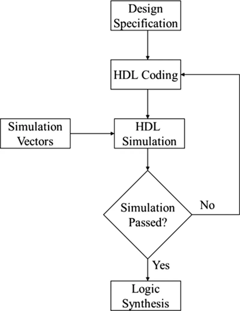
Figure 1.1 HDL design flow
What this book covers
This is a book about designing digital circuits with Verilog and SystemVerilog. It assumes no prior knowledge of Verilog or any HDL. It covers language syntax and best practices for producing reliable digital-integrated circuits. It includes hundreds of examples showing how the various constructs are used to effectively create hardware designs. It also includes numerous examples of test fixtures to verify the correct functioning of the provided design examples.
This book takes the reader from a design specification through a verified design ready for synthesis.
Covered are all parts of Verilog and SystemVerilog that are useful for circuit design as well as some components of the languages that are needed for verification but are not meaningful for circuit description.
SystemVerilog is an all-encompassing language that can be used for a variety of verification and even unrelated programming tasks that are not fundamental to hardware design. Constructs that are not directly related to hardware design are not covered.
Historical perspective
The earliest integrated circuits were designed at the subtransistor level. Individually crafting each transistor, a team of four engineers took 4 months to complete the first microprocessor. That processor, the four-bit Intel® 4004, used 2300 transistors. It went into production in 1971.
As this book is being written, some state of the art processors have upwards of three billion transistors. If engineers still work at the same rate of transistor design, a team of four would take nearly half a million years to turn out a new processor.
The density of transistors that could be formed on a single die increased exponentially over the past four decades as semiconductor manufacturing prowess improved. With the increase in transistor density, crafting each transistor individually became an untenable methodology. The necessity of developing ever-larger circuits led to the creation of more abstract models of combinational and sequential functions that could be reused in schematic representations of new circuits.
Designing at the gate level rather than at the transistor level and increasing the size of the design teams were the next steps in design methodology and management. These moves decreased the time to complete designs by orders of magnitude, but the inexorable increase in semiconductor density opened the doors to newer design methodologies. Unlike transistor density, design team size could not increase exponentially, year after year, for decades.
Verifying the behavior of these ever more complex circuit designs before committing to building the first prototype was another challenge. Simulations of the logical behavior of an abstract design became standard operating procedure, yet as design complexity continued to accelerate, determining if designs were logically correct became ever more difficult and time consuming.
It was to address verification challenges that what became HDLs were first developed. Building on earlier work with proprietary simulation languages, Philip Moorby and Prabhu Goel developed the first version of the Verilog language in the winter of 1983–1984 at their then-young startup company Gateway. At the same time, several companies were developing the earliest logic synthesis programs.
While it is implicit in the name (Verilog is formed from the words verify logic) that the foci of efforts at Gateway were simulation and verification, the language’s designers from the beginning were intent on using it for circuit specification and synthesis. Synopsys® was the first to license the new language for circuit synthesis from HDL code. At the time, it was a symbiotic relationship, as Synopsys did not then sell simulators and Gateway did not do logic synthesis.
Gateway was eventually bought by design automation company Cadence®, which does compete in the synthesis arena, and Synopsys has now long been in the simulation business as well as logic synthesis.
From its origins as a proprietary language, Verilog was released as an open standard in 1990 and in 1995 became an IEEE standard, IEEE 1364-1995. The standard has been updated and expanded several times, most recently by merging it with SystemVerilog, the object-oriented superset of Verilog. SystemVerilog is IEEE standard 1800.
When digital design with hardware description was new and engineers already had vast experience designing with schematic diagrams, there was some resistance to adopting the new HDL design paradigms. Early versions of the tools were far less capable than those of today. Fewer language constructs were supported and optimization was not as effective. At the beginning, there was some concern about the ability of automatic tools to generate correct gate-level circuits. Even once a high level of confidence that logic synthesis could produce logically correct circuits was obtained, engineers who had spent years and even decades optimizing gate-level designs remained convinced that they could obtain higher-quality results manually than any computer program could turn out.
Since there may have been some truth to that conviction when logic synthesis was first introduced, the HDL and synthesis design flow was first adopted by application-specific integrated circuit (ASIC) designers, for whom getting a completely new design into production quickly was more valued than squeezing the ultimate in clock speed out of a design. With a large foundation of highly optimized gate-level designs, processor developers were resistant to changing their fundamental design practices and procedures. While there was nothing inherently application specific about the HDL–synthesis design flow, it became known as ASIC methodology.
With improvements in design automation tools and under pressure to develop ever larger circuits with ever shorter design cycles, the ASIC methodology moved into less speed critical portions of processors and other catalog parts and then conquered the entire design process. Today using anything other than HDL and synthesis for digital design would be eccentric and anachronistic. It is used everywhere in the world where digital-integrated circuits are made and for products ranging from the simplest...
Table of contents
- Cover
- Title page
- Table of Contents
- Copyright Page
- About the author
- Preface
- Acknowledgments
- Chapter 1: Introduction
- Chapter 2: Bottom-up design
- Chapter 3: Behavioral coding part I: blocks, variables, and operators
- Chapter 4: Behavioral coding part II: defines, parameters, enumerated types, and packages
- Chapter 5: Behavioral coding part III: loops and branches
- Chapter 6: Subroutines and interfaces
- Chapter 7: Synchronization
- Chapter 8: Simulation, timing, and race conditions
- Chapter 9: Architectural choices
- Chapter 10: Design for testability
- Chapter 11: Library modeling
- Chapter 12: Design examples
- Appendix A: SystemVerilog keywords
- Appendix B: Standard combinational and sequential functions
- Appendix C: Number systems
- Index
Frequently asked questions
Yes, you can cancel anytime from the Subscription tab in your account settings on the Perlego website. Your subscription will stay active until the end of your current billing period. Learn how to cancel your subscription
No, books cannot be downloaded as external files, such as PDFs, for use outside of Perlego. However, you can download books within the Perlego app for offline reading on mobile or tablet. Learn how to download books offline
Perlego offers two plans: Essential and Complete
- Essential is ideal for learners and professionals who enjoy exploring a wide range of subjects. Access the Essential Library with 800,000+ trusted titles and best-sellers across business, personal growth, and the humanities. Includes unlimited reading time and Standard Read Aloud voice.
- Complete: Perfect for advanced learners and researchers needing full, unrestricted access. Unlock 1.5M+ books across hundreds of subjects, including academic and specialized titles. The Complete Plan also includes advanced features like Premium Read Aloud and Research Assistant.
We are an online textbook subscription service, where you can get access to an entire online library for less than the price of a single book per month. With over 1.5 million books across 990+ topics, we’ve got you covered! Learn about our mission
Look out for the read-aloud symbol on your next book to see if you can listen to it. The read-aloud tool reads text aloud for you, highlighting the text as it is being read. You can pause it, speed it up and slow it down. Learn more about Read Aloud
Yes! You can use the Perlego app on both iOS and Android devices to read anytime, anywhere — even offline. Perfect for commutes or when you’re on the go.
Please note we cannot support devices running on iOS 13 and Android 7 or earlier. Learn more about using the app
Please note we cannot support devices running on iOS 13 and Android 7 or earlier. Learn more about using the app
Yes, you can access Digital Integrated Circuit Design Using Verilog and Systemverilog by Ronald W. Mehler in PDF and/or ePUB format, as well as other popular books in Design & Hardware. We have over 1.5 million books available in our catalogue for you to explore.