Abstract:
Thermal barrier coatings (TBCs), which offer excellent properties in terms of high-temperature operating, thermal barrier and flow- and wear-resistance, have been developed for application in hot-section components of gas turbines. Research in this area has become a new direction in the surface engineering field. Electron beam physical vapor deposition (EB–PVD) has received much research attention in recent years since it offers many advantages for TBCs.This chapter introduces the structure and preparation processes of TBCs. Two-layer structured TBCs were prepared by EB–PVD on superalloy IC10/IC6. The behavior of TBCs under thermal cycling was investigated. The roughness of the bond coat was found to have a significant effect on the lifetime of TBCs, the lifetime clearly decreasing during thermal cyclic testing as the roughness average (Ra) of the bond coat increased. The thickness of the pre-oxide layer also affected the lifetime of TBCs, the lifetime decreasing during thermal cyclic testing as the pre-oxide layer thickness increased. Graded thermal barrier coatings were prepared by EB–PVD on superalloy and the thermal cycling behavior was investigated.
1.1 Introduction
There are many methods of preparing thermal barrier coatings (TBCs), such as electron beam physical vapor deposition (EB–PVD), plasma spray, high-velocity oxy-fuel (HVOF), sol–gel, laser chemical vapor deposition, and so on.1–8 At the time of writing EB–PVD and plasma spray have become popular preparation methods. Plasma spray has a simpler equipment structure than EB–PVD, and thermal spray has a higher spray rate than EB–PVD.
For plasma spray, it is not necessary to heat the substrate, and the deposition rate is much faster than that of EB–PVD. However, coatings prepared by EB–PVD are different from those prepared by plasma spray. EB–PVD TBCs have better surface roughness than those produced by plasma spray, which means that EB–PVD TBCs have good aerodynamics. EB–PVD TBCs have a columnar crystal microstructure and those produced by plasma spray a laminated structure. Due to good resistance to spallation from the substrate, TBCs with the columnar structure obtained by EB–PVD have a longer lifespan than those with the laminated structure obtained by plasma spray during thermal cycling. Therefore, EB–PVD TBCs are likely to become popular in the future.
1.1.1 Electron beam physical vapor deposition (EB–PVD) technology and its equipment
Since the 1980s, EB–PVD has been investigated for preparation of TBCs. A significant development in the 1990s was the invention by Paton Electric Institute of Welding in Ukraine of a new EB–PVD technology which decreased the preparation cost of EB–PVD TBCs. This technology has been widely applied in the production of TBCs.
The electron beam has a very important role as the thermal source of EB–PVD technology. EB–PVD is capable of depositing any type of material. The deposition mechanism consists of an electron beam formed at 2000 °C in an electron gun (either a Pierce gun or an electromagnetism deflexion gun), followed by acceleration of thermal electrons under high voltage. When the high-speed electrons hit materials in the ingot, energy is generated sufficient to melt and convert material into vapor and then deposit it onto the substrate. Compared to other preparation methods, this method has a higher deposition rate. Moreover, deposition parameters can be easily controlled and the surface is very smooth with a Ra surface value of about 1–2 μm. There is a strong adhesion between the substrate and coatings after deposition by EB–PVD. Process parameters are easily modified and the deposition rate can be accurately controlled.
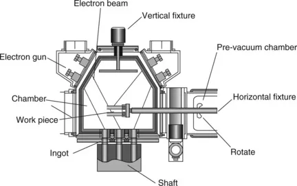
The EB–PVD equipment is more complex compared to other methods. Figure 1.1 gives a diagram of EB–PVD equipment (UE205). There are four electron guns, two sets of sample fixtures (one vertical and one horizontal), three ingots, and two chambers (one of which is a pre-vacuum chamber) in this EB–PVD system. Three electron guns are used to heat the materials in the ingots, respectively, and one electron gun to heat the substrate (work-piece) to achieve the right deposition condition which is able to ensure good adhesion between substrate and coatings. During depositing, the sample fixture keeps rotating to get a stable substrate temperature and uniform coating thickness. Three ingots can deposit from one to three types of material and prepare coatings of different structures. There is a shaft below the material in the ingot. During depositing, the shaft pushes the material up to the ingot, thus increasing the deposition rate. EB–PVD equipment of different types with different structures can prepare TBCs of different shapes and structures. For example, some EB–PVD equipment (UE-206, UE204U) has six electron guns and more power.
1.1 EB–PVD equipment (UE205).
1.1.2 Thermal barrier coatings (TBCs): structure
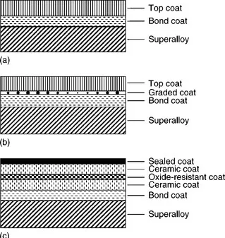
There are three types of EB–PVD TBCs: two-layered, graded, and multi-layered. As shown in Fig. 1.2, two-layered structured TBCs are traditional TBCs comprising a bond coat with MCrAlY(M = Ni, Co) and a ceramic top coat with 6–8 wt% Y2O3 stabilized ZrO2. Graded TBCs (GTBCs) can relax the stress between the top coat and the bond coat which is brought by different coefficients of thermal expansion. In the GTBCs system, there is a transition layer with Al2O3 between the bond coat and the top coat. Multi-layered TBCs are usually used for specialist applications. In the future, it is likely that nanostructure TBCs will have an important role because they have the capacity to enhance the effectiveness of the thermal barrier.
1.2 TBC structures: (a) two-layered; (b) graded; (c) multi-layered.
1.2 Preparation process and parameters
TBCs should be prepared under optimum preparation conditions and parameters. Many preparation parameters can affect the quality of TBCs. Amonst these, three – vacuum pressure, substrate temperature, and deposition rate – can have a significant effect.
1.2.1 Vacuum pressure
O2 pressure dictates the vacuum pressure in the chamber. If O2 exists in the chamber, it will decrease the background vacuum. This is because O2 can result in filament oxidation of t...